1. Introduction
This manual provides comprehensive instructions for the assembly, setup, operation, and maintenance of your Generic Hu-052 LED Music Spectrum Display DIY Kit. This kit is designed for enthusiasts interested in electronics and offers a rewarding experience in building a functional music spectrum display. Please read this manual thoroughly before beginning assembly to ensure correct and safe operation.
2. Safety Information
- Always disconnect power before performing any assembly or maintenance.
- Handle electronic components with care to avoid damage from static electricity. Consider using an anti-static wrist strap.
- Soldering should be performed in a well-ventilated area. Avoid inhaling solder fumes.
- Keep small components out of reach of children to prevent choking hazards.
- Ensure all connections are correct before applying power to prevent short circuits or component damage.
3. Package Contents
Before starting assembly, verify that all components listed below are present in your kit. If any parts are missing or damaged, please contact customer support.
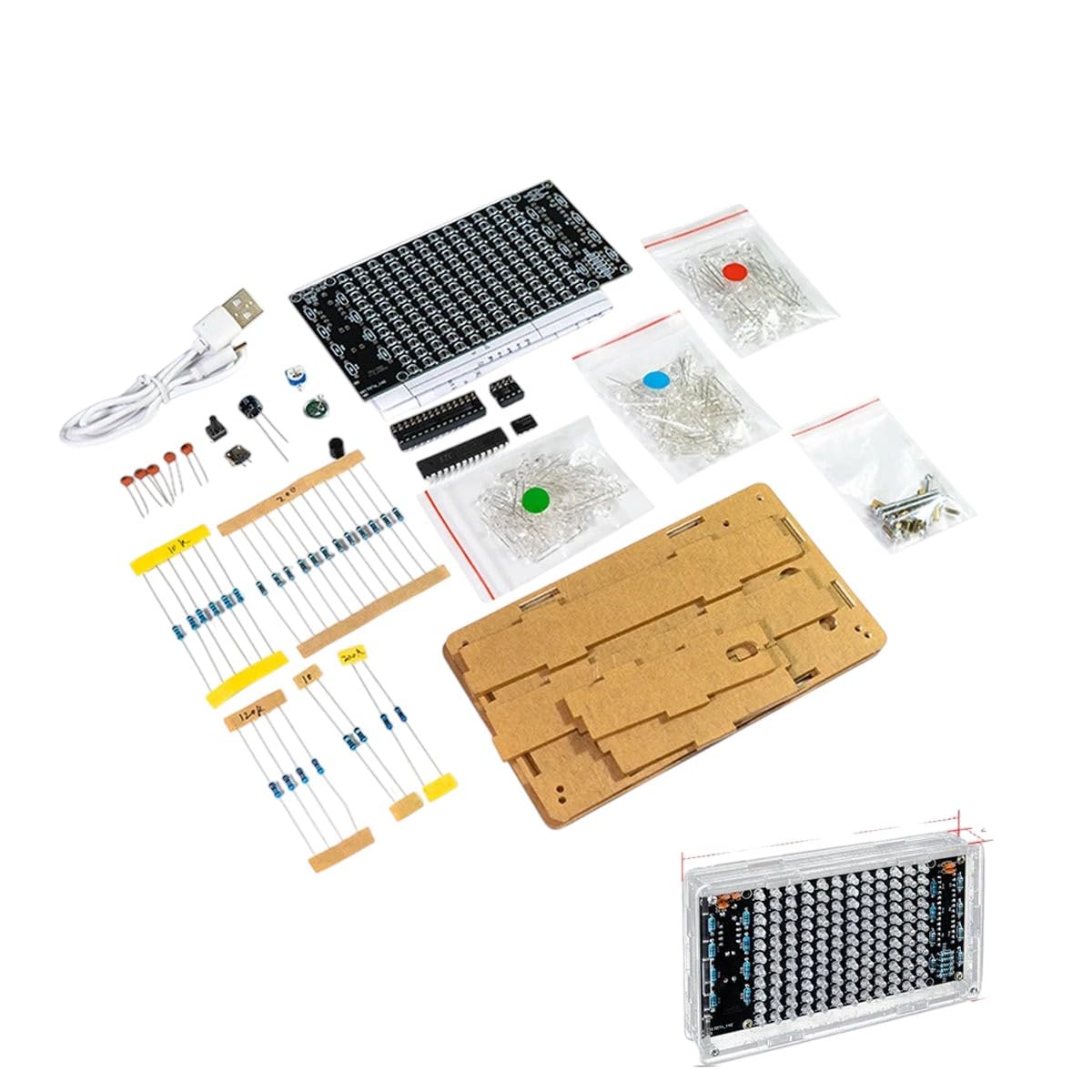
Figure 3.1: Overview of the Hu-052 LED Music Spectrum Display DIY Kit components. This image displays the main circuit board, various resistors, capacitors, LEDs, integrated circuits, a USB power cable, and acrylic casing parts, all neatly organized for assembly.
- Main Circuit Board (PCB)
- LED Matrix (individual LEDs or pre-assembled module)
- Resistors (various values)
- Capacitors (electrolytic and ceramic)
- Integrated Circuits (ICs) and Sockets
- Diodes
- Transistors
- Microphone Module (for audio input)
- Power Jack/USB Cable
- Acrylic Casing Parts
- Fasteners (screws, nuts, standoffs)

Figure 3.2: A close-up view of various electronic components typically found in the kit, including integrated circuits, capacitors, resistors, and LEDs. These are the individual parts that will be soldered onto the circuit board.

Figure 3.3: An isometric illustration depicting various semiconductor and electronic components such as integrated circuits, capacitors, resistors, and diodes. This visual aid helps in identifying different component types.
4. Assembly Instructions
Follow these steps carefully to assemble your LED Music Spectrum Display. It is recommended to have basic soldering skills and tools (soldering iron, solder, desoldering wick/pump, wire cutters, multimeter) before starting.
- Component Identification: Sort all components and identify them using the provided component list and circuit diagram (if included). Pay attention to resistor color codes and capacitor polarity.
- Resistor Installation: Solder all resistors onto the PCB. Start with the lowest height components first. Bend the leads, insert into the correct holes, and solder from the underside. Trim excess leads.
- Diode Installation: Solder diodes, ensuring correct polarity (match the band on the diode to the marking on the PCB).
- Capacitor Installation: Solder ceramic capacitors (non-polarized) and then electrolytic capacitors. For electrolytic capacitors, ensure the longer lead (positive) matches the '+' marking on the PCB, and the shorter lead (negative) matches the '-' or shaded area.
- IC Socket Installation: Solder the IC sockets onto the PCB. Ensure the notch on the socket aligns with the notch marking on the PCB. Do not insert the ICs yet.
- LED Installation: Solder the LEDs. LEDs are polarized; the longer lead is positive (+), and the shorter lead is negative (-). Match these to the PCB markings.
- Other Components: Install any remaining components such as the microphone module, power jack, and switches.
- IC Insertion: Carefully insert the Integrated Circuits into their respective sockets. Ensure the notch on the IC aligns with the notch on the socket and PCB. Bend the pins slightly inward if necessary to fit.
- Casing Assembly: Assemble the acrylic casing around the completed circuit board using the provided screws and standoffs. Ensure all parts fit snugly and are secured.
5. Setup
Once assembly is complete, follow these steps to set up your LED Music Spectrum Display:
- Power Connection: Connect the provided USB power cable to the display's power input port and then to a 5V USB power adapter (not included) or a computer USB port.
- Audio Input: The display typically uses a built-in microphone to detect ambient sound. Ensure the microphone is not obstructed.
- Placement: Place the display in a location where it can easily pick up audio from your music source.

Figure 5.1: The fully assembled Hu-052 LED Music Spectrum Display enclosed in its clear acrylic casing, ready for power connection and operation. This view highlights the LED matrix and the overall compact design.
6. Operating Instructions
Once powered on, the display will automatically begin to react to sound. Here’s how to use it:
- Power On: Connect the USB power. The LEDs should light up, indicating the device is active.
- Sound Detection: Play music or generate sound near the display. The LED columns will illuminate and fluctuate in height, representing different frequency bands of the audio spectrum.
- Adjusting Sensitivity (if applicable): Some kits may include a potentiometer to adjust the microphone sensitivity. If present, gently turn the knob to fine-tune how the display reacts to sound levels.
- Power Off: Disconnect the USB power cable to turn off the display.
7. Maintenance
- Cleaning: Use a soft, dry cloth to clean the acrylic casing. Avoid abrasive cleaners or solvents that could damage the plastic.
- Dust Removal: Periodically use compressed air to remove dust from the circuit board and microphone area to ensure optimal performance.
- Component Check: If the display malfunctions, visually inspect soldered joints for cold solder joints or bridges. Re-solder as necessary.
8. Troubleshooting
| Problem | Possible Cause | Solution |
|---|---|---|
| Display does not power on. | No power, faulty USB cable, incorrect soldering. | Check USB connection and power source. Inspect all solder joints for continuity and shorts. |
| LEDs are dim or uneven. | Incorrect resistor values, faulty LEDs, cold solder joints. | Verify resistor values. Check LED polarity. Re-solder any suspicious joints. |
| Display does not react to sound. | Microphone module not connected or faulty, incorrect IC insertion, sensitivity too low. | Ensure microphone module is correctly soldered and connected. Verify IC orientation. Adjust sensitivity potentiometer if available. |
| Some LED columns are not working. | Faulty LEDs, incorrect soldering for specific columns, IC issue. | Check individual LEDs and their solder joints. Verify connections to the driving ICs. |
9. Specifications
- Model: Hu-052
- Input Voltage: 5V DC (via USB)
- Audio Input: Built-in Microphone
- Display Type: LED Matrix
- Material: Electronic components, Metal, Acrylic casing
- Operating Temperature: Standard
10. Warranty and Support
This DIY kit is provided for educational and hobbyist purposes. Due to the nature of a DIY product, warranty coverage typically applies to manufacturing defects of individual components upon receipt, not errors during assembly. Please inspect all components upon arrival.
For technical assistance, missing parts, or inquiries regarding component defects, please contact the seller through the platform where the product was purchased. Provide your order number and a detailed description of the issue for prompt support.
Manufacturer: Generic


