Introduction
This manual provides comprehensive instructions for the installation, operation, and maintenance of your JRAHK 36V-52V 350W E-Bike Controller Kit. This kit is designed to convert standard bicycles into electric bikes, and is also suitable for electric scooters and tricycles. Please read this manual thoroughly before installation and use to ensure safe and optimal performance.
The kit offers a complete solution, pairing a high-performance controller with a smart LCD throttle for a simplified DIY experience. It is compatible with a wide range of brushless motor vehicles.
Product Components
The JRAHK E-Bike Controller Kit includes the following items:
- 1 x Golden Aluminum Alloy BLDC Controller (36V/48V/52V, 350W)
- 1 x Multi-function LCD Display Throttle (24V-72V Compatible)
- 1 x Set of Necessary Wiring and Connectors

This image displays the complete JRAHK E-Bike Controller Kit, including the golden aluminum alloy brushless DC controller, the LCD display throttle, and the associated wiring harnesses with various connectors.
Technical Specifications
Controller Specifications:
- Material: Aluminum Alloy
- Voltage: 36V / 48V / 52V (Auto-identifying)
- Rated Power: 350W
- Current Limit: 12A - 18A
- Type: Brushless DC Controller
Throttle Specifications:
- Voltage: 24V-72V (Default 48V)
- Display: LCD Screen
- Wire Length: 1.8 meters
General Product Information:
- Product Dimensions (Controller): 1.6 x 1.6 x 3.1 inches (40.6 x 40.6 x 78.7 mm)
- Item Model Number: CON007-6G LCD Kit
- Weight: Approximately 1.72 Pounds (777g)
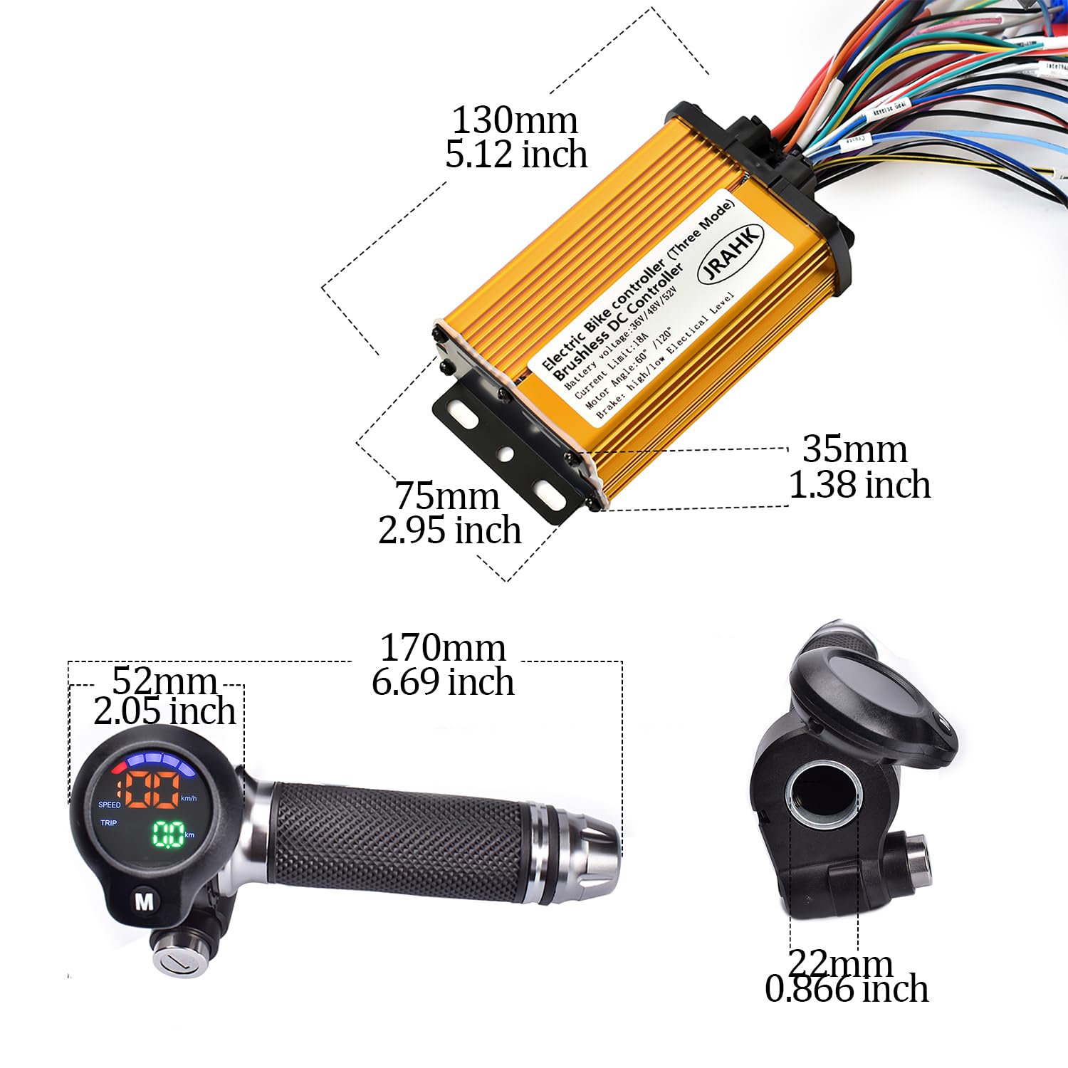
This diagram illustrates the physical dimensions of the controller and the LCD display throttle, providing measurements in both millimeters and inches for accurate planning and installation.

This image visually confirms the voltage compatibility (36V-48V-52V), maximum current (18A), and power output range (250W-350W) of the controller.
Setup and Installation
This kit is designed for plug-and-play installation. Ensure your motor type and battery voltage are compatible before proceeding with any connections.
Wiring Diagram Overview:
Refer to the following diagram for an overview of the controller's wiring connections. Each connection is numbered for easy identification.

This diagram provides a comprehensive guide to the controller's wiring, labeling each connector with a number and its corresponding function, such as motor phase wire, power cord, throttle, and sensor connections.
- Motor phase wire
- Power cord
- Key switch
- Phase line speed measurement
- One-line communication
- Three-speed shifting
- Anti-theft signal
- Anti-theft power supply
- Hall sensor
- Hall speed test
- Intelligent learning line
- Throttle
- Reversal
- PAS (Pedal Assist System)
- High level braking
- Low level braking
- Cruising
Detailed Wire Color Descriptions:
Understand the function of each wire by its color code for correct connection.

This image shows specific wire connectors and their associated color codes, detailing functions such as Hall speed wire (Brown), Phase line speed measurement (Orange), High/Low speed (Dark Blue/Light Blue), Power+/Electric door lock (White/Yellow), and 5V power supply/signal/GND (Red/Green/Black).
- Brown: Hall speed wire
- Orange: Phase line speed measurement
- Dark blue: High speed
- Light blue: Low speed
- White: Power+
- Yellow: Electric door lock
- Red: 5V power supply
- Green: Signal line
- Black: GND
Speed Measurement Connections:
Depending on your setup, you will use either phase line speed measurement or Hall speed measurement. Ensure the corresponding P03 parameter is set correctly.

This diagram illustrates how to connect the phase line speed measurement wire from the controller to the throttle. If using this method, ensure P03 setting is adjusted to '1'.
Phase Line Speed Measurement: Connect the designated wire. If using this method, set the P03 parameter to 1 in the LCD display settings.

This diagram illustrates how to connect the Hall speed measurement wire from the controller to the throttle. If using this method, ensure P03 setting is adjusted to '2'.
Hall Speed Measurement: Connect the designated wire. If using this method, set the P03 parameter to 2 in the LCD display settings.
Operating Instructions
The multi-function LCD display throttle provides clear real-time data and allows for parameter adjustments to customize your riding experience.
LCD Display Functions:
- Speed Display: Shows current riding speed (km/h or mph).
- Battery Level: Indicates remaining battery charge.
- Distance: Tracks trip distance.
- Error Codes: Displays diagnostic codes for troubleshooting.
- Riding Modes: Allows switching between different power assist levels.
Parameter Settings (P00-P09):
Access these settings via the LCD display to customize your riding experience. Consult your display's specific instructions for how to enter and navigate the parameter settings menu.

This table details the various programmable parameters (P00-P09) accessible through the LCD display, including voltage, speed measurement magnification, mileage correction, motor wheel diameter, number of motor magnets, battery voltage correction, gear settings, and unit selection (km/miles).
| Parameter | Description |
|---|---|
| P00 | Voltage: 24V/36V/48V/60V/72V. Default 48V. |
| P01 | Phase line speed measurement magnification. For example, if the actual speed is 30 and the display shows 25, you can increase the P01 value. Default value 100. |
| P02 | Mileage correction. |
| P03 | Speed measurement type: 1. Phase line speed measurement. 2. Hall speed test. Default 2. |
| P04 | Motor wheel diameter. Used for speed measurement. The larger the wheel diameter setting, the faster the corresponding speed displayed. |
| P05 | Number of motor magnets. Can be used to adjust Hall speed measurements. The larger the setting value, the slower the display speed. |
| P06 | Battery voltage correction. |
| P07 | Gear setting: 1st gear, 2nd gear, 3rd gear. Default setting is 0. |
| P08 | The total mileage is cleared 10 times. |
| P09 | Unit selection: 1. km. 2. miles. Default kilometers. |
Maintenance
Proper maintenance ensures the longevity and reliable performance of your E-Bike Controller Kit.
- Cleaning: Regularly wipe the controller and display with a soft, dry cloth. Avoid using harsh chemicals or excessive moisture.
- Connections: Periodically check all wiring connections to ensure they are secure and free from corrosion. Loose connections can lead to intermittent operation or damage.
- Heat Dissipation: Ensure the controller's aluminum alloy casing is not obstructed to allow for proper heat dissipation. Overheating can reduce component lifespan.
- Storage: When not in use for extended periods, store the kit in a dry, cool environment, away from direct sunlight and extreme temperatures.
Troubleshooting
The LCD display can show error codes to help diagnose issues. Refer to your display's specific error code guide for detailed interpretations. Below are common issues and general solutions:
- No Power: Check battery connections, ensure the key switch (if used) is on, and verify the main power cord connection to the controller. Confirm battery voltage is within the compatible range.
- Motor Not Responding: Check motor phase wires and Hall sensor connections for secure fit. Ensure the throttle is correctly connected and functioning. Verify that the intelligent learning line has been used to pair the controller and motor.
- Incorrect Speed Display: Verify P03 setting (Phase line vs. Hall speed measurement) and P04 (motor wheel diameter) are correctly configured according to your setup.
- Intermittent Operation: Inspect all wiring for loose connections, frayed wires, or damage. Ensure all connectors are fully seated.
If issues persist after performing these checks, it is recommended to consult a qualified technician or contact JRAHK customer support for further assistance.
Warranty and Support
For warranty information or technical assistance, please refer to the seller's policy or contact JRAHK customer support directly. Keep your purchase receipt as proof of purchase.
You can visit the official JRAHK store for more information and support resources: JRAHK Store on Amazon.