1. Introduction
This manual provides essential information for the safe and efficient installation, operation, and maintenance of your Cwmiibili P2.5 Indoor Full Color LED Display Unit Board. Please read this manual thoroughly before using the product to ensure proper functionality and to prevent damage.
Safety Information
- Ensure all power connections are secure and correctly polarized before applying power.
- Do not expose the LED display unit to moisture or extreme temperatures. This product is designed for indoor use only.
- Avoid direct eye contact with the LED panel when it is operating at high brightness.
- Only use specified power and data cables.
- Disconnect power before performing any maintenance or installation procedures.
2. Product Overview
The Cwmiibili P2.5 Indoor Full Color LED Display Unit Board is a high-resolution LED module designed for various indoor display applications. It features a full-color SMD RGB configuration, providing vibrant and clear visuals.
Key Features
- Usage: Indoor applications
- Tube Chip Color: Full Color (SMD RGB)
- Module Size: 320x160mm
- Pixel Resolution: 128x64 pixels
- Pixel Pitch: P2.5
- Interface: HUB75
Package Contents
Each package typically includes:
- LED Display Unit Board(s)
- Power Cord(s)
- Data Cable(s) (typically flat ribbon cable for HUB75)

Image 2.1: Contents of the package, showing an LED display unit board, a power cable (red and black wires), and a data ribbon cable.
Note: The appearance of the module backplane may vary between different production batches. This variation does not affect the functionality or performance of the unit.
3. Setup and Installation
Proper installation is crucial for the optimal performance and longevity of your LED display unit. Follow these steps carefully.
3.1 Component Identification

Image 3.1: Rear view of the LED display unit board, highlighting the HUB75 data input/output ports and the DC power input connector.
- HUB75 Connectors: These are the standard 16-pin (or similar) connectors for data input and output, typically labeled 'IN' and 'OUT' or with arrows.
- Power Input: A 4-pin power connector (2 red, 2 black wires) for DC power supply.
- Mounting Holes: Screw holes located around the perimeter for securing the module to a frame or cabinet.
3.2 Connecting Multiple Modules (Cascading)
For larger displays, multiple LED unit boards can be connected in series. The data output of one module connects to the data input of the next.
- Power Connection: Connect the power cable from a suitable DC power supply (typically 5V) to the power input of each LED module. Ensure correct polarity (red for positive, black for negative). For multiple modules, ensure the power supply can handle the total current draw.
- Data Connection:
- Connect the data ribbon cable from your LED controller card (e.g., Novastar, Linsn, Colorlight) to the HUB75 'IN' port of the first LED module.
- Connect another data ribbon cable from the HUB75 'OUT' port of the first module to the 'IN' port of the second module.
- Repeat this process for all subsequent modules in the chain.
- Mounting: Securely mount each LED module to a rigid frame or cabinet using appropriate screws. Ensure the modules are aligned correctly to form a seamless display.
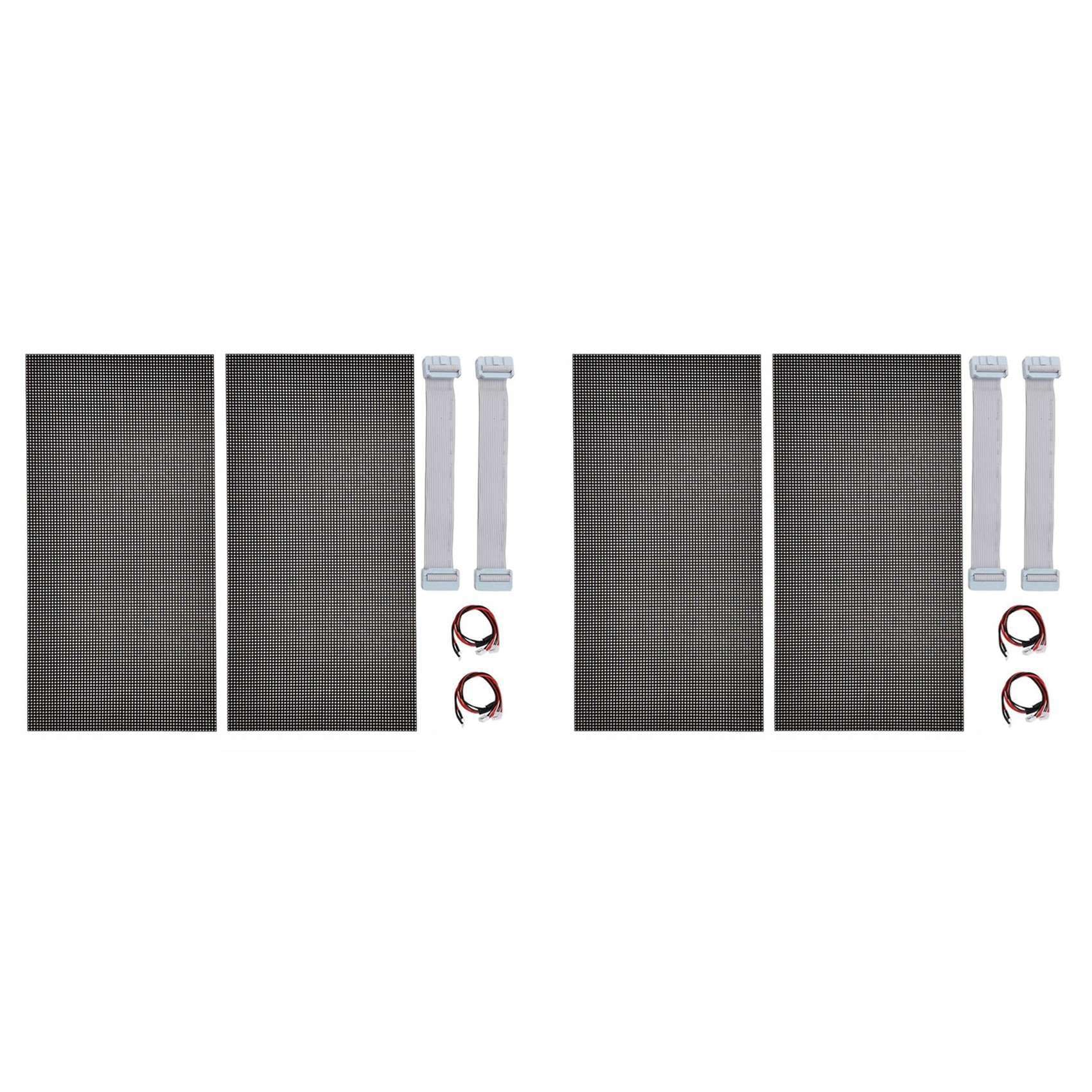
Image 3.2: Detailed view of the back of an LED module, showing the arrangement of components and connectors. The note indicates that the back panel appearance may vary by batch but functionality remains consistent.
4. Operating Instructions
Once the LED display unit boards are physically installed and connected, configuration via an LED control system is required to display content.
4.1 System Requirements
- LED Controller Card: A compatible LED sending card (e.g., Novastar, Linsn, Colorlight) is required to send video signals to the display.
- Control Software: Software provided by the LED controller manufacturer (e.g., Novastar LCT, Linsn LED Studio) is necessary for display configuration and content management.
- Power Supply: A stable 5V DC power supply with sufficient current capacity for all connected modules.
4.2 Basic Configuration Steps (General)
- Connect Controller: Connect your LED controller card to your computer via USB or Ethernet, and to the first LED module via the HUB75 data cable.
- Install Software: Install the appropriate control software on your computer.
- Power On: Apply power to the LED modules and the controller card.
- Software Setup:
- Open the control software and detect the connected controller card.
- Configure the display parameters, including the number of modules (width and height in modules), pixel pitch (P2.5), and scanning mode (often automatically detected or found in module specifications).
- Perform screen calibration if necessary to ensure uniform brightness and color.
- Load Content: Once configured, you can load images, videos, or other content through the software to be displayed on the LED screen.
5. Maintenance
Regular maintenance helps preserve the performance and lifespan of your LED display units.
- Cleaning: Gently wipe the surface of the LED modules with a soft, lint-free cloth. For stubborn dirt, slightly dampen the cloth with a mild, non-abrasive cleaning solution. Do not spray liquids directly onto the panel.
- Dust Removal: Use a soft brush or compressed air to remove dust from connectors and ventilation areas.
- Connection Check: Periodically inspect all power and data cable connections to ensure they are secure.
- Environmental Control: Maintain a stable indoor environment, avoiding high humidity and extreme temperature fluctuations.
6. Troubleshooting
This section addresses common issues you might encounter with your LED display unit.
| Problem | Possible Cause | Solution |
|---|---|---|
| No display/Black screen | No power, loose power cable, controller not sending signal, incorrect software configuration. | Check power supply and connections. Verify controller status and software settings. Ensure correct module parameters are set in the software. |
| Partial display/Garbled image | Loose data cable, incorrect data cable connection order, incorrect software configuration (e.g., scan mode, module dimensions). | Check data ribbon cable connections between modules and to the controller. Ensure 'IN' and 'OUT' ports are correctly used. Re-verify software configuration for module arrangement and scan settings. |
| Individual LEDs not working | Damaged LED pixel. | Individual LED pixels are generally not user-replaceable. If multiple pixels are affected, consider replacing the module. |
| Inconsistent brightness/color | Power supply issues, software calibration needed, faulty module. | Ensure stable power supply. Perform software calibration. If issue persists on a specific module, it may be faulty. |
7. Specifications
| Parameter | Value |
|---|---|
| Brand | Cwmiibili |
| Model Number | I750205232 (P2.5) |
| Usage Environment | Indoor |
| Tube Chip Color | Full Color (SMD RGB) |
| Module Size | 320x160mm |
| Pixel Resolution | 128x64 pixels |
| Pixel Pitch | 2.5mm |
| Interface | HUB75 |
| Material | Plastic + Electronic Components |
8. Warranty Information
This product is covered by a standard manufacturer's warranty against defects in materials and workmanship. The specific terms and duration of the warranty may vary. Please retain your proof of purchase for warranty claims. For detailed warranty information, refer to the documentation provided at the time of purchase or contact the seller directly.
9. Support
For technical assistance, troubleshooting beyond this manual, or inquiries regarding your Cwmiibili P2.5 Indoor Full Color LED Display Unit Board, please contact your point of purchase or the manufacturer's customer support. When contacting support, please have your model number (I750205232) and purchase details ready.