1. Introduction
This manual provides detailed instructions for the installation, operation, and maintenance of your Temank PowMr MPPT Solar Charge Controller POW-RV1245A. This advanced Maximum Power Point Tracking (MPPT) controller is designed to efficiently manage power from your solar panels to charge 12V/24V battery systems, including lead-acid and lithium batteries. It features high tracking efficiency and comprehensive protection mechanisms to ensure optimal performance and safety for off-grid systems, RVs, and small cabins.
2. Safety Information
Please read all safety instructions carefully before installation and operation. Failure to follow these instructions may result in personal injury, damage to the controller, or damage to other components in your system.
- Ensure all connections are correct and secure before applying power. Incorrect wiring can cause damage.
- Always disconnect the PV input before modifying any USER-mode charging parameters via the remote screen to prevent setting errors and ensure safe configuration.
- The controller is designed for indoor use in a well-ventilated area. Avoid exposure to direct sunlight, high temperatures, or moisture.
- Do not disassemble or attempt to repair the controller yourself. Contact qualified personnel for service.
- Ensure proper grounding of the system as per local electrical codes.
- Wear appropriate personal protective equipment (PPE) when working with electrical systems, including insulated gloves and eye protection.
3. Product Overview
The Temank PowMr MPPT Solar Charge Controller POW-RV1245A is designed for efficient and reliable solar power management. Key features include:
- Advanced MPPT Technology: Up to 99% tracking efficiency for optimal energy harvest.
- Intuitive Rotary Knob: Simplifies battery type selection (SEL, GEL, FLD, L04, L08, USER) without complex menu navigation.
- Wide Compatibility: Works with 12V/24V lead-acid and lithium batteries.
- Comprehensive Protection: Includes PV and battery reverse polarity, over-current, short-circuit, and over-temperature protection.
- Silent Operation: Fanless design for natural heat dissipation.
- Optional Remote Monitoring: Supports an optional remote control screen (sold separately) for real-time data and parameter adjustment.
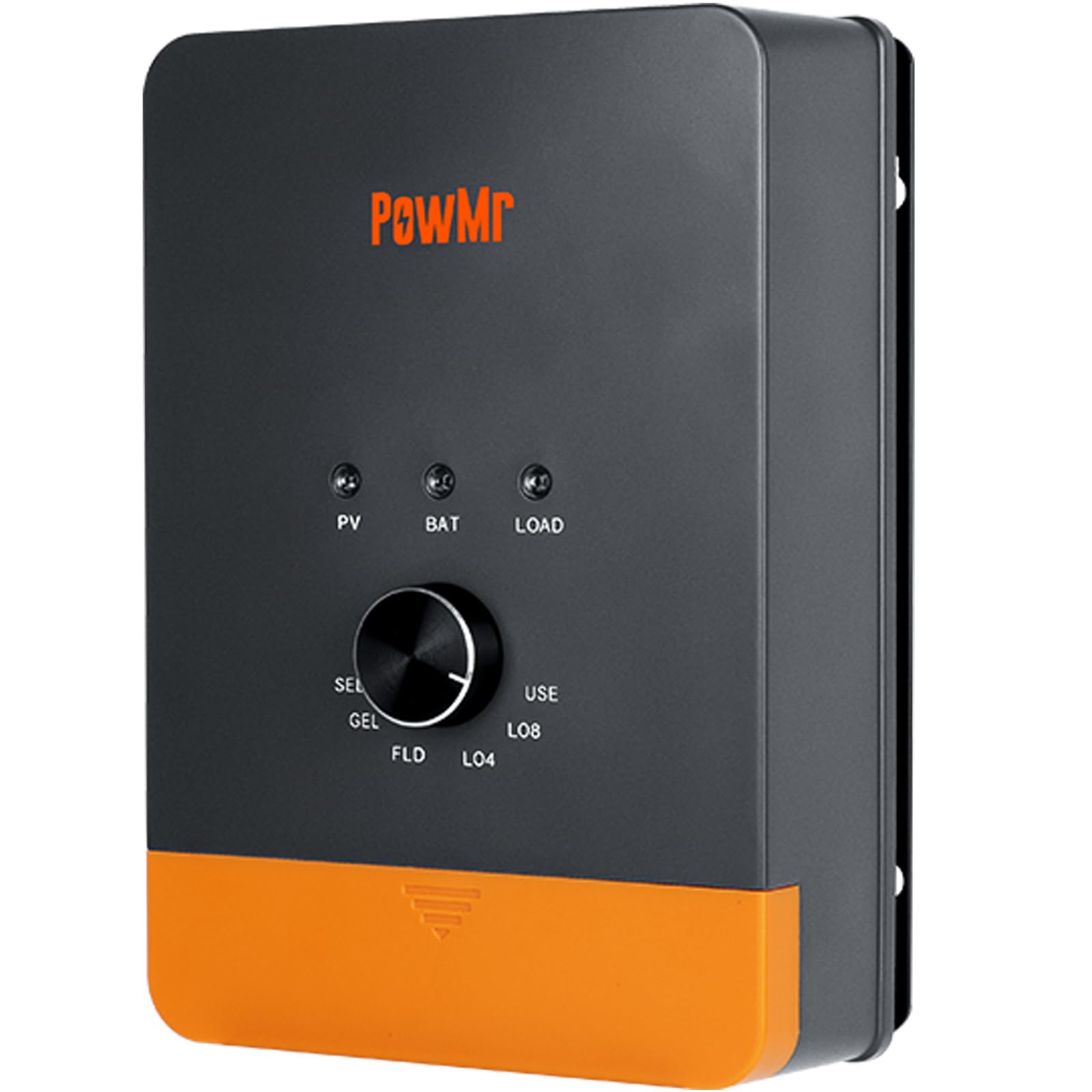
Figure 3.1: Temank PowMr MPPT Solar Charge Controller POW-RV1245A connected in a solar system setup.
4. Setup and Installation
Follow these steps for proper installation of your solar charge controller.
4.1 Mounting the Controller
Mount the controller vertically on a non-flammable surface in a well-ventilated area. Ensure sufficient clearance around the unit for proper heat dissipation. Avoid mounting in direct sunlight or areas with high humidity.
4.2 Wiring Connections
Connect the system components in the following order to ensure safety and proper operation:
- Connect the Battery: First, connect the battery to the controller's battery terminals. Ensure correct polarity (positive to positive, negative to negative). The controller will automatically detect the system voltage (12V or 24V).
- Connect the Load (Optional): If using the load output, connect your DC load to the controller's load terminals. Ensure correct polarity.
- Connect the PV Array: Finally, connect the solar panel array to the controller's PV terminals. Ensure correct polarity. The controller will begin charging.
Important: Disconnect the system in the reverse order: PV array, then Load, then Battery.

Figure 4.1: Schematic wiring diagram for the solar charge controller. Connect battery first, then load, then PV. Disconnect in reverse order.
5. Operating Instructions
5.1 Battery Type Selection
The controller features a rotary knob for easy selection of battery types. Rotate the knob to select the appropriate battery chemistry for your system. The available options are:
- SEL: Sealed lead-acid battery
- GEL: Gel sealed lead-acid battery
- FLD: Flooded lead-acid battery
- L04: 4S Lithium iron phosphate battery (LiFePO4)
- L08: 8S Lithium iron phosphate battery (LiFePO4)
- USER: User-defined settings (requires optional remote screen for adjustment)
Note: For 24V lead-acid or USER type systems, the actual charging voltage is double the display value (e.g., a 14.4V setting will result in 28.8V output).
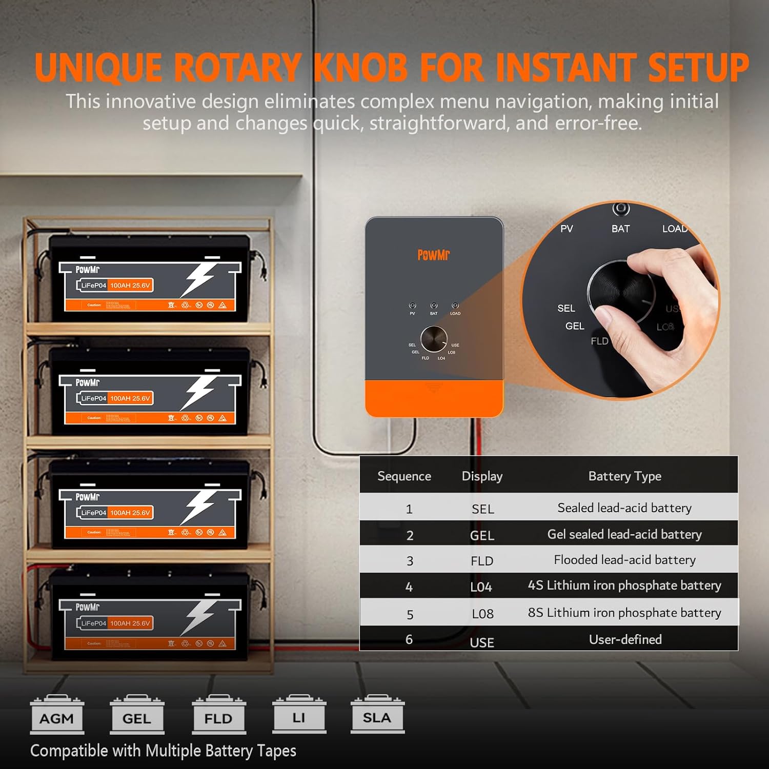
Figure 5.1: Rotary knob for selecting battery type.
5.2 MPPT Charging Mode (Three-Stage Charging)
The controller utilizes a three-stage charging algorithm to optimize battery life and performance:
- Bulk Charge: Charges the battery at its maximum current until the voltage reaches the boost voltage.
- Boost Charge: Maintains the boost voltage for a set period to ensure full charge.
- Float Charge: Reduces the voltage to a lower level to maintain the battery at full charge and prevent overcharging.
An equalization charge is performed once a month for compatible battery types to prevent sulfation and ensure cell balance.

Figure 5.2: Three-stage charging profile for prolonged battery lifecycle.
5.3 Optional Remote Control Screen
An optional remote control screen (sold separately) can be connected to the controller for advanced monitoring and parameter adjustment. This allows real-time data viewing and modification of settings, including load control modes, providing greater flexibility for your system.
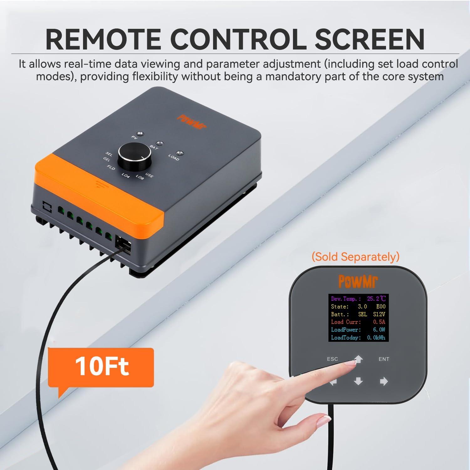
Figure 5.3: Optional remote control screen for monitoring and parameter adjustment.
6. Maintenance
Regular maintenance ensures the longevity and optimal performance of your solar charge controller and system.
- Inspect Connections: Periodically check all wiring connections for tightness and corrosion. Loose connections can cause overheating and power loss.
- Clean the Controller: Keep the controller clean and free from dust and debris. Use a dry cloth to wipe the exterior. Do not use liquid cleaners.
- Ventilation: Ensure that the area around the controller remains clear to allow for proper airflow and heat dissipation.
- Battery Inspection: Regularly inspect your batteries for any signs of damage, leakage, or swelling. Ensure battery terminals are clean.
7. Troubleshooting
This section provides solutions to common issues you might encounter.
- No Power/Display:
- Check battery connections and ensure correct polarity.
- Verify battery voltage is within the operating range (12V/24V).
- Ensure the battery is not completely discharged.
- No Charging from PV:
- Check PV array connections and polarity.
- Ensure sufficient sunlight is reaching the solar panels.
- Verify PV open-circuit voltage is within the controller's specifications (Max. PV Input 100V for 45A model).
- Over-temperature Protection:
- Ensure adequate ventilation around the controller.
- Reduce load or PV input if operating in extremely hot environments.
- Battery Not Fully Charged:
- Confirm the correct battery type is selected using the rotary knob.
- Check for sufficient PV input power and sunlight hours.
- Inspect battery health and capacity.
For persistent issues, refer to the detailed specifications or contact customer support.
8. Specifications
| Feature | Specification |
|---|---|
| Model | POW-RV1245A |
| System Voltage | 12V/24V Auto |
| Rated DC Output Current | 45A |
| Max. PV Input Open-Circuit Voltage | 100V |
| Max. Input Power (12V Battery) | 540W |
| Max. Input Power (24V Battery) | 1080W |
| Tracking Efficiency | Up to 99% |
| Peak Conversion Efficiency | Up to 97% |
| Display Type | Knob |
| Dimensions | 7.6" x 5.2" x 2.65" (approximate) |
| Net Weight | 2.1 lbs (approximate) |
| Operating Temperature | -20°C to +55°C |
| Protection Features | PV/Battery Reverse Polarity, Over-current, Short-circuit, Over-temperature, Over-discharging, Overcharging, Overload, Reverse Current Compensation |

Figure 8.1: Certified protections for the solar charge controller.
9. Warranty and Support
Information regarding product warranty and customer support was not available in the provided product data. Please refer to the product packaging or the manufacturer's official website for details on warranty coverage and how to contact customer support for technical assistance or service.