1. Introduction
The Y&H 3600W Solar Inverter is a multi-function inverter/charger designed to provide uninterruptible power support. It integrates the functions of an inverter, solar charger, and battery charger into a compact unit. This device features a comprehensive LCD display and user-configurable button operations for managing battery charging current, AC/solar charger priority, and acceptable input voltage based on various application requirements.
Key Features:
- Pure sine wave solar inverter (on/off Grid)
- Built-in 120A MPPT Solar Charger
- High PV input voltage range (90~450VDC)
- Supports 24V batteries (AGM, Gel, Lead Acid, Lithium-ion, Lithium Iron Phosphate) and battery-free operation
- Dual AC output (110V/120V)
- LCD display and LED indicators for real-time monitoring
- Intelligent variable speed fan for effective heat dissipation
- Comprehensive protection functions including short circuit, overload, overcharge, overcurrent, overvoltage, undervoltage, and over-temperature.
2. Safety Instructions
Please read all instructions and warnings in this manual carefully before installation and operation. Failure to follow these instructions may result in electric shock, fire, or severe injury. Keep this manual for future reference.
- Ensure all wiring is performed by qualified personnel.
- Do not disassemble the inverter. There are no user-serviceable parts inside.
- Install the inverter in a well-ventilated area, away from flammable materials.
- Ensure proper grounding for the inverter.
- Verify correct battery voltage and polarity before connecting.
- Disconnect all power sources (PV, AC, Battery) before performing any maintenance or wiring.
3. Product Overview
The Y&H 3600W Solar Inverter is designed for efficient power conversion and management in solar energy systems. It features a robust design with clear indicators and connection points.

Figure 3.1: Front view of the Y&H 3600W Solar Inverter, illustrating its 3600W AC output power, 120VAC output voltage, 24V DC input voltage, 120A MPPT solar charge controller, 60-450VDC PV input voltage range, and 90V starting voltage. It also highlights pure sine wave hybrid inverter with dual AC output, compatibility with lead-acid and lithium batteries, battery-free use, and support for solar, utility, or generator power.
4. Installation and Setup
Proper installation is crucial for the safe and efficient operation of the inverter. Follow these guidelines carefully.
4.1 Wiring Diagram
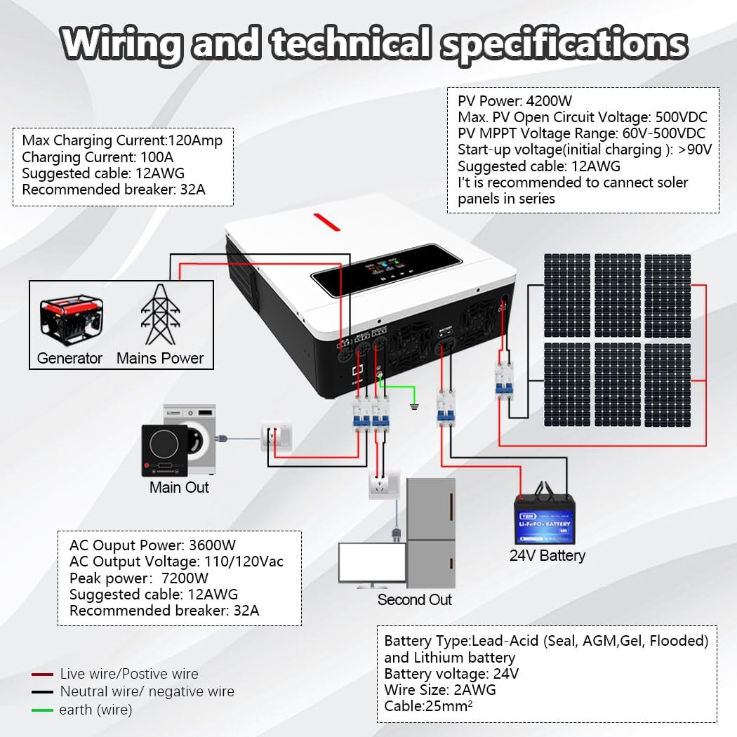
Figure 4.1: Detailed wiring diagram showing connections for generator, mains power, main output, second output, 24V battery, and solar panels. Technical specifications for PV power, open circuit voltage, MPPT voltage range, start-up voltage, max charging current, AC output power, peak power, and recommended cable gauges are also displayed.
Refer to the diagram for connecting the solar panels, battery, AC input (mains/generator), and AC outputs (main and second load). Ensure all connections are secure and use the recommended cable gauges.
4.2 Battery Connection
- Connect a 24V battery bank to the inverter's battery terminals.
- Ensure correct polarity: positive to positive, negative to negative.
- The inverter is compatible with AGM, Gel, Lead Acid, Lithium-ion, and Lithium Iron Phosphate batteries.
- For lithium batteries, ensure proper BMS communication if required by the battery manufacturer.
4.3 PV Array Connection
- Connect solar panels to the PV input terminals.
- Ensure the total PV array power does not exceed 4200W.
- The maximum DC voltage from the PV array should not exceed 500VDC.
- The starting voltage for solar charging is greater than 90V.
- It is recommended to connect solar panels in series to achieve the optimal voltage range.
4.4 AC Input and Output Connection
- Connect the AC mains power or generator to the AC input terminals.
- Connect your loads to the Main Out and Second Out AC output ports.
- The inverter provides 110V/120V AC dual output.
- Ensure appropriate circuit breakers are installed for AC input and output lines.
5. Operation
Once installed, the inverter can be configured and operated using its LCD display and control buttons.
5.1 LCD Display and Indicators

Figure 5.1: The LCD screen and LED indicators provide dynamic display of system data and operating status, allowing users to monitor the inverter's performance.
The LCD display provides real-time information on battery status, charging current, output voltage, and operational modes. The LED indicators offer quick visual status updates.
5.2 Charging Modes
The inverter offers four user-configurable charging modes:

Figure 5.2: Diagram illustrating the four charging modes (CSO Solar First, Utility First, SNU Solar and Utility, OSO Only Solar) and three discharge modes (SUB Solar First, USB Utility First, SBU Priority) to optimize energy use.
- Only Solar (OSO): Charges the battery exclusively from solar power.
- Mains Supply Priority (UTI): Prioritizes charging from the AC utility grid, with solar as a backup.
- Solar Priority (SOP): Prioritizes charging from solar power, with the AC utility grid as a backup.
- Combination of Mains Supply and Solar Charging (SNU): Utilizes both solar and AC utility power for charging.
5.3 Output Modes
The inverter supports two output modes:
- Power Bypass: Loads are directly powered by the AC utility grid when available.
- Inverter Output: Loads are powered by the inverter, drawing energy from the battery or solar.
5.4 Dual Load Output Function
The inverter features a dual load output, allowing for prioritized power delivery.

Figure 5.3: Diagram illustrating the dual load output functionality. The main output port stops working when the battery voltage falls below a set range (20V-23V), while the secondary output port continues to operate.
The 4.2KW model has a configurable setting range for the main output port from 20.0V to 23.0V, adjustable in 0.1V increments. If the battery voltage drops below this set range, the main output port will cease operation. The secondary output port, however, will continue to function. This feature is useful in areas with frequent power outages or for loads that require continuous power, allowing users to prioritize critical loads on the secondary output.
5.5 Battery Compatibility and Battery-Free Operation

Figure 5.4: The Y&H Inverter supports seamless multi-battery connectivity with AGM, GEL, FLD (Flooded), LI (Lithium), and SLD (Sealed Lead Acid) batteries. It also supports battery-free operation.
The inverter is compatible with various 24V battery types, including AGM, Gel, Lead Acid, Lithium-ion, and Lithium Iron Phosphate. It also supports a battery-free operation mode, allowing the system to run directly from solar and/or AC input without a connected battery. Built-in lithium battery activation and comprehensive battery protection functions (short circuit, over/under voltage) are included to optimize battery life.
6. Maintenance
Regular maintenance ensures the longevity and optimal performance of your inverter.
- Cleaning: Periodically clean the inverter's exterior with a dry cloth. Ensure ventilation openings are free from dust and debris.
- Connections: Annually check all electrical connections (PV, battery, AC input/output) for tightness and corrosion.
- Environment: Ensure the installation environment remains within specified temperature and humidity ranges.
- Battery Inspection: If using batteries, regularly inspect them for any signs of damage, leakage, or swelling. Follow battery manufacturer's maintenance guidelines.
7. Troubleshooting
If the inverter is not functioning as expected, refer to the following basic troubleshooting steps. For complex issues, contact customer support.
- No Power/Display: Check all power connections (battery, AC input). Ensure the main power switch is on. Verify battery voltage is within the operational range.
- No AC Output: Check if the inverter is in bypass mode. Verify battery voltage. Check for overload conditions or short circuits on the output.
- No Solar Charging: Ensure PV panels are connected correctly and receiving sunlight. Check PV input voltage is within the specified range (90-450VDC).
- Error Codes: If the LCD displays an error code, consult the full product manual (if available) or contact customer support with the specific code.
- Overload Protection: If an overload occurs, the inverter may shut down. Reduce the load and restart the inverter.
8. Specifications
Technical specifications for the Y&H 3600W Solar Inverter, Model NM-ECO-LV-3.6K-110V.
| Specification | Value |
|---|---|
| Model Number | NM-ECO-LV-3.6K-110V |
| Manufacturer | Y&H |
| ASIN | B0FQMT4FRN |
| Power Source | Solar Powered |
| Max. PV Array Power | 4200W |
| Max. DC Voltage (PV) | 500VDC |
| MPPT Voltage Range | 90~450VDC |
| Starting Voltage (PV) | > 90V |
| Rated Power | 3600W |
| Peak Power | 7200W |
| AC Output Voltage | 110V/120V |
| Output Frequency | 50Hz/60Hz |
| Max AC Input Current | 40A |
| Battery Voltage | 24VDC |
| Max. Charging Current | 120A |
| Recommended Uses | Home, Office, Vehicle |
| UPC | 704334627192 |
9. Warranty and Support
For warranty information, technical support, or service inquiries, please contact Y&H customer service through your purchase platform or the official Y&H website. Please have your model number (NM-ECO-LV-3.6K-110V) and purchase date ready when contacting support.