
1. Introduction
The BoltBlaze 30KM Rechargeable Visual Fault Locator (VFL) is a robust and portable tool designed for identifying faults in fiber optic cables. It emits a high-intensity 650nm red laser light that allows users to visually locate breaks, bends, poor connections, or cracks in fiber optic cables over distances of up to 30 kilometers. This manual provides essential information for the safe and effective use of your VFL.
2. Important Safety Information
WARNING: LASER RADIATION. AVOID DIRECT EYE EXPOSURE. CLASS II LASER PRODUCT.
- Never look directly into the laser output port or into a fiber connected to the VFL.
- Do not point the laser at people or animals.
- Use caution when operating the VFL, as the laser light can be harmful to the eyes.
- Keep the device out of reach of children.
- Ensure the protective cap is on the VFL when not in use.
3. Package Contents
Verify that all items listed below are included in your package:
- BoltBlaze Visual Fault Locator (VFL)
- FC to LC Adapter
- USB-C Charging Cable
- Wrist Strap

Figure 3.1: All items included in the BoltBlaze VFL package.
4. Product Overview
Familiarize yourself with the components of your BoltBlaze VFL:
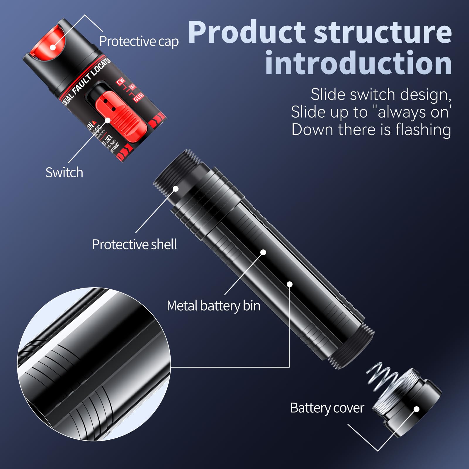
Figure 4.1: VFL Product Structure. Key components include the protective cap, mode switch, main body, and battery compartment.
The VFL features a slide switch for operation and mode selection. The device is constructed with an aluminum alloy body for durability and includes a metal head with a ceramic core for reliable performance.

Figure 4.2: Universal 2.5mm Connector Compatibility. The VFL is compatible with ST, SC, and FC interfaces, and includes an FC to LC adapter for broader use.
5. Setup
5.1 Charging the VFL
The BoltBlaze VFL is equipped with an 800mAh lithium-ion battery and supports USB-C charging. Before first use, or when the battery is low, charge the device using the provided USB-C cable.
- Connect the USB-C cable to the charging port on the VFL.
- Connect the other end of the USB-C cable to a standard USB power adapter (not included) or a computer's USB port.
- The charging indicator (if present) will show the charging status. A full charge typically provides several hours of operation.

Figure 5.1: Charging the BoltBlaze VFL via USB-C.
5.2 Attaching Adapters
The VFL has a standard 2.5mm universal connector. For LC fiber optic cables, use the included FC to LC adapter.
- Remove the protective cap from the VFL's output port.
- If using an LC connector, gently insert the FC end of the FC to LC adapter into the VFL's output port until it is secure.
- Ensure the adapter is clean before attachment.
6. Operating Instructions
6.1 Powering On and Selecting Modes
The VFL features a slide switch for power and mode selection:
- Slide the switch to the 'ON' position for continuous wave (CW) mode. The laser will emit a steady red light.
- Slide the switch to the 'GLINT' or 'PULSE' position for pulsed mode. The laser will emit a flashing red light, which can be useful for easier fault identification in certain conditions.
- Slide the switch to the 'OFF' position to turn off the VFL.

Figure 6.1: VFL Operating Modes: Continuous Wave (CW) and Pulse.
6.2 Connecting to Fiber and Fault Detection
To detect faults in a fiber optic cable:
- Ensure the fiber optic cable is disconnected from any active network equipment.
- Clean the fiber optic connector end face thoroughly.
- Remove the protective cap from the VFL's output port.
- Gently insert the cleaned fiber optic connector into the VFL's output port (or the attached adapter).
- Turn on the VFL to either CW or Pulse mode.
- Observe the fiber along its length. Red light escaping from the fiber indicates a fault, such as a break, bend, or poor splice.
- Once testing is complete, turn off the VFL and replace the protective cap.
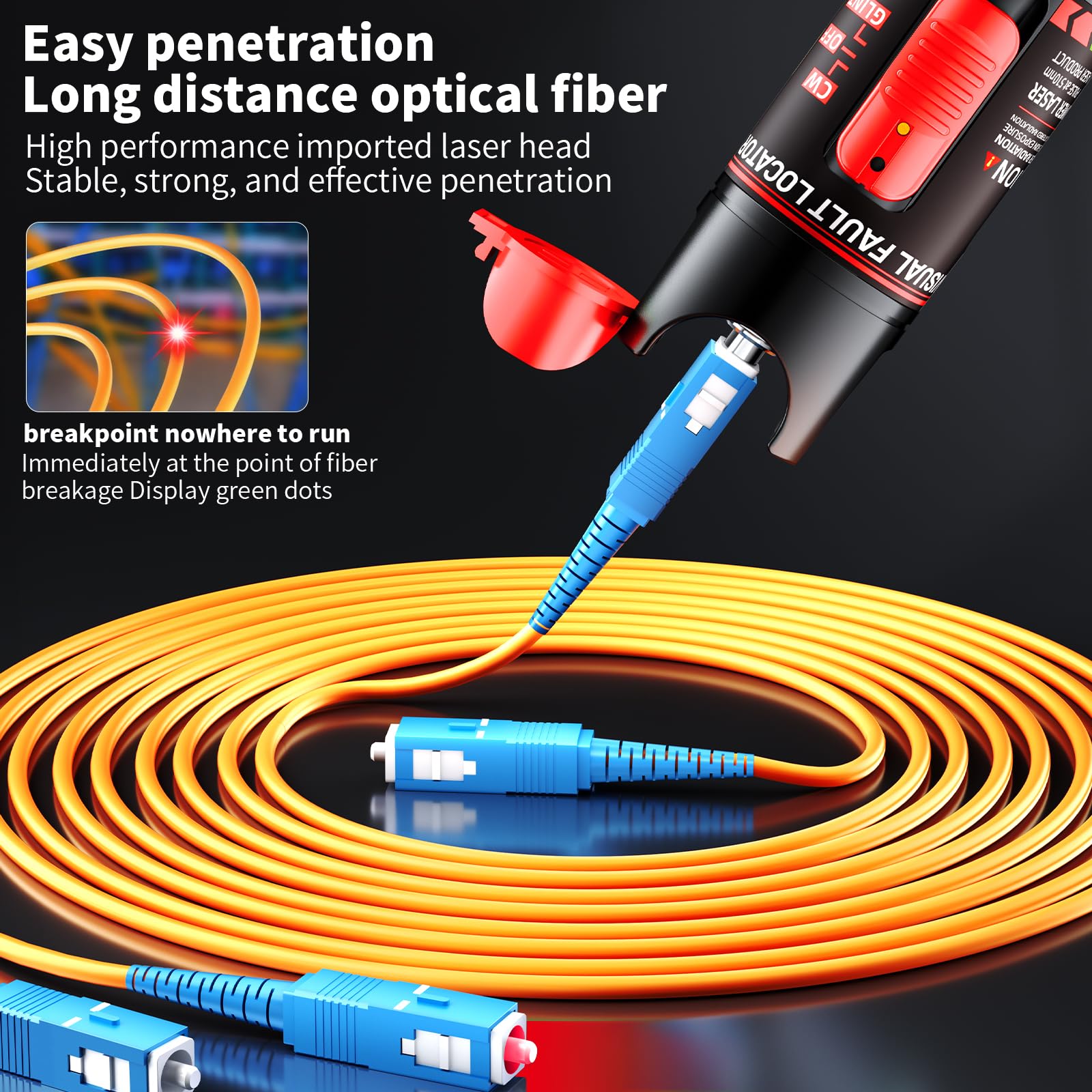
Figure 6.2: Detecting a breakpoint in a fiber optic cable using the VFL.
7. Maintenance
7.1 Cleaning the VFL Tip and Fiber Connectors
Regular cleaning is crucial for accurate measurements and to prevent damage to the VFL and fiber optic cables.
- Always ensure the VFL is turned off before cleaning.
- Use a lint-free wipe and isopropyl alcohol to gently clean the VFL's output port and any adapters.
- For fiber optic connectors, use specialized fiber optic cleaning tools (e.g., one-click cleaners, cleaning sticks) to clean the end faces.
- Never use abrasive materials or solvents that could damage the optical components.

Figure 7.1: The VFL features a durable metal head with a ceramic core, which should be kept clean.
7.2 Storage
- Store the VFL in a dry, dust-free environment.
- Always replace the protective cap on the VFL's output port when not in use.
- If storing for an extended period, ensure the battery is partially charged (around 50%) to prolong its lifespan.
8. Troubleshooting
| Problem | Possible Cause | Solution |
|---|---|---|
| No laser light output | Battery is depleted Device is off Output port blocked | Charge the VFL Slide switch to 'ON' or 'GLINT' Check for debris and clean the output port |
| Weak or inconsistent laser light | Low battery Dirty connector/port Damaged fiber | Recharge the VFL Clean VFL output port and fiber connector Inspect fiber for damage |
| Cannot detect fault | Fiber connector not properly seated Fault is beyond VFL's range Fiber is too dirty | Ensure fiber connector is fully inserted Confirm fault is within 30KM range Thoroughly clean fiber connector |
9. Specifications
- Model: 30km-Rechargeable
- Wavelength: 650nm
- Output Power: Not specified, but capable of 20-30km detection
- Detection Distance: 20-30 kilometers
- Connector Type: Universal 2.5mm (compatible with ST, SC, FC); includes FC to LC adapter
- Battery: 800mAh Lithium Ion (rechargeable via USB-C)
- Modes: Continuous Wave (CW), Pulse (GLINT)
- Material: Aluminum alloy body, metal head with ceramic core
- Dimensions: Approximately 5.9 inches (150mm) in length, 0.98 inches (25mm) in diameter
- Weight: Approximately 4.23 ounces (120g)

Figure 9.1: VFL dimensions for portability.
10. Warranty and Support
For warranty information, technical support, or service inquiries, please contact BoltBlaze customer service through the retailer where the product was purchased or visit the official BoltBlaze website. Please retain your proof of purchase for warranty claims.