1. Introduction
The AIKWEIK Solderless Breadboard Kit provides a convenient and reusable platform for prototyping electronic circuits without the need for soldering. This kit is ideal for experimenting with circuit designs, testing components, and educational purposes. It allows for quick assembly and modification of circuits, making it an essential tool for hobbyists, students, and engineers.
This manual provides detailed instructions on the components included, setup, operation, and maintenance of your solderless breadboard kit.
2. Package Contents
Verify that all items listed below are present in your package:
- Solderless Breadboards: A total of 8 pieces, comprising a mix of 830, 400, and 170 tie-point boards. This specific kit variant also includes an additional 4 pieces of 170 tie-point breadboards.
- 65 pieces of Flexible Breadboard Jumper Wires
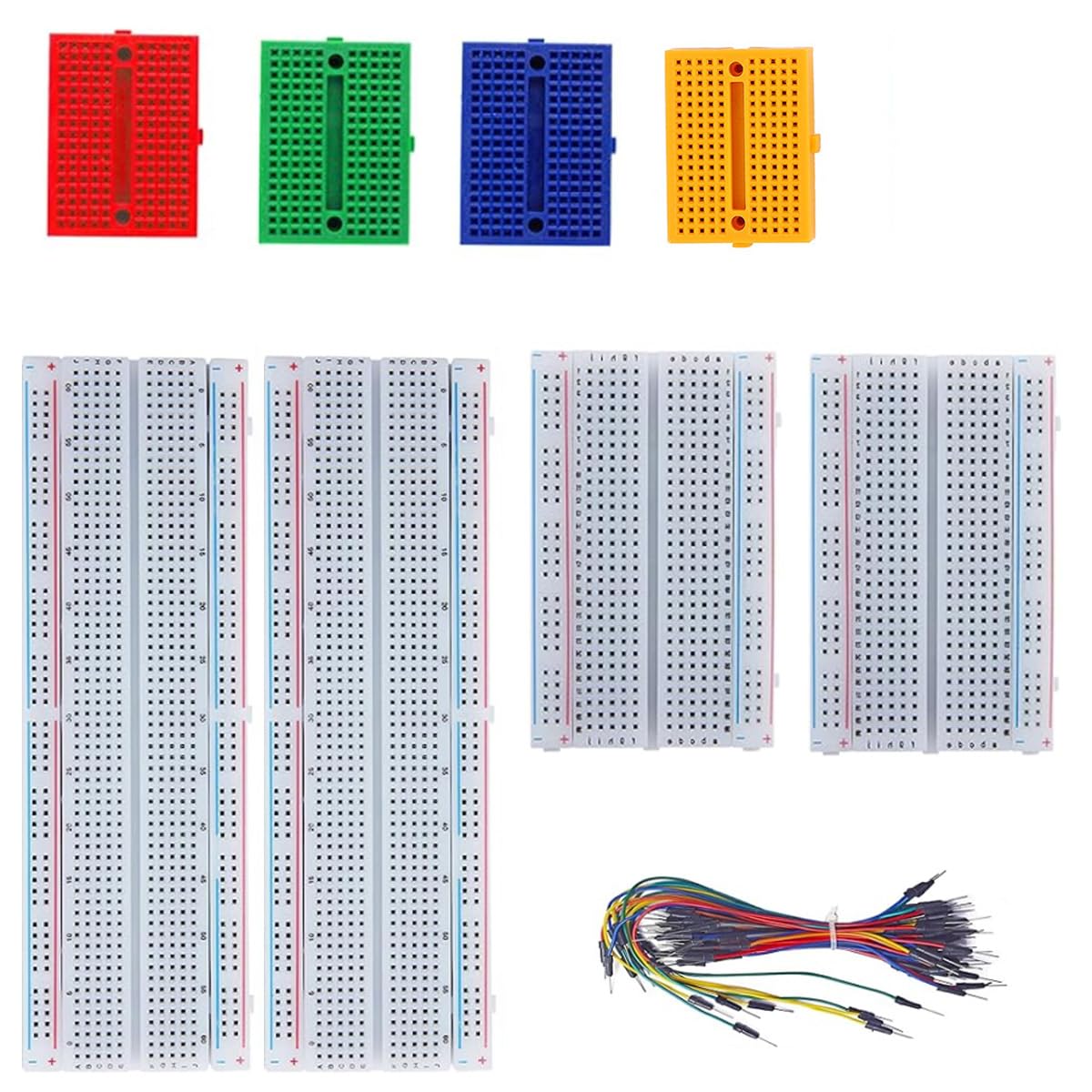
Figure 2.1: The AIKWEIK Solderless Breadboard Kit showing various sizes of breadboards and a bundle of jumper wires. This image illustrates the typical components included in the kit, ready for electronic prototyping.
3. Product Features
The AIKWEIK Solderless Breadboard Kit offers the following key features:
- Solderless Design: Enables temporary prototyping and testing of circuit designs without permanent soldering.
- Reusable: Components can be easily inserted and removed, allowing for multiple circuit iterations.
- Internal Connections: Metal strips underneath the board connect holes. Top and bottom rows (power rails) are connected horizontally and split in the middle. Remaining holes are connected vertically.
- Expandable: Breadboards can be spliced together to create larger prototyping areas.
- Clear Structure: Color-coded sections for easy identification of power rails and component areas.
- Durable Material: Constructed from ABS Plastic Panel with Tin Plated Phosphor Bronze Contact Sheet for reliable connections.
- Versatile Kit: Includes various breadboard sizes (830, 400, 170 tie points) and flexible jumper wires for diverse project needs.
4. Setup
Setting up your solderless breadboard for a project is straightforward:
- Select the Appropriate Breadboard: Choose a breadboard size (830, 400, or 170 tie points) that best fits the complexity and number of components for your circuit.
- Understand the Connections:
- Power Rails (Horizontal): The long rows along the top and bottom edges are typically used for power supply connections (e.g., +5V, GND). These rows are connected horizontally. Note that on larger breadboards, these rails are often split in the middle, requiring a jumper wire to connect both halves if a continuous rail is needed.
- Component Area (Vertical): The central area consists of columns of five holes each, connected vertically. Components are typically inserted across the central channel (the "ditch") to prevent short circuits between their pins.
- Prepare Components: Ensure component leads are straight and clean. Trim leads if they are excessively long.
- Plan Your Layout: Before inserting components, it's helpful to sketch your circuit diagram and plan the physical layout on the breadboard to optimize space and minimize wire clutter.
5. Operating Instructions
Follow these steps to build and test your circuits:
- Insert Components: Gently push the leads of your electronic components (resistors, capacitors, ICs, etc.) into the desired holes on the breadboard. Ensure they are firmly seated. For integrated circuits (ICs), place them across the central channel so that pins on opposite sides are in different vertical columns.
- Make Connections with Jumper Wires: Use the provided flexible jumper wires to connect different points on the breadboard according to your circuit diagram.
- Connect power supply to the power rails.
- Connect component pins to other component pins or power rails using jumper wires.
- Keep wires neat and organized to avoid confusion and potential errors.
- Apply Power: Once all components are correctly placed and connections are made, connect your power supply to the designated power rails on the breadboard. Double-check all connections before applying power to prevent damage to components.
- Test and Debug: Use a multimeter or oscilloscope to test different points in your circuit. If the circuit does not function as expected, carefully review your connections against the circuit diagram and troubleshoot any discrepancies.
- Modify and Experiment: The solderless nature of the breadboard allows for easy modification. You can quickly swap components, change connections, and experiment with different circuit configurations.
6. Maintenance
Proper maintenance ensures the longevity and reliability of your breadboards:
- Keep Clean: Regularly clean the breadboards to remove dust, debris, and any residue from component leads. A soft brush or compressed air can be used.
- Avoid Force: Do not force component leads or jumper wires into the holes. This can damage the internal metal clips, leading to intermittent connections.
- Store Properly: When not in use, store breadboards in a clean, dry environment, away from direct sunlight and extreme temperatures.
- Inspect Contacts: Periodically inspect the holes for any signs of damage or corrosion. Damaged holes may result in poor electrical contact.
7. Troubleshooting
If you encounter issues with your circuit on the breadboard, consider the following:
| Problem | Possible Cause | Solution |
|---|---|---|
| Circuit not working / Intermittent connections | Loose jumper wire or component lead; damaged internal clip; incorrect wiring. | Ensure all connections are firm. Try wiggling wires to identify loose connections. Replace damaged breadboard sections or wires. Double-check wiring against schematic. |
| Component overheating | Incorrect power supply voltage; reversed polarity; short circuit. | Immediately disconnect power. Verify power supply voltage and polarity. Check for accidental short circuits between component pins or power rails. |
| Power rails not working across entire length | Split power rail on larger breadboards. | Add a jumper wire to connect the two halves of the power rail if a continuous connection is required. |
8. Specifications
Key specifications for the AIKWEIK Solderless Breadboard Kit:
- Manufacturer: AIKWEIK
- Model Number: ADD 4PCS 170
- Material: ABS Plastic Panel, Tin Plated Phosphor Bronze Contact Sheet
- Tie Points: Assortment includes 830, 400, and 170 tie-point breadboards
- Included Components: Solderless Breadboards, 65 pcs Flexible Breadboard Jumper Wires
- ASIN: B0FQBN4MWB
9. Warranty and Support
AIKWEIK products are designed for quality and reliability. For any questions, technical assistance, or support regarding your Solderless Breadboard Kit, please refer to the retailer's return policy or contact AIKWEIK customer service through the platform where the product was purchased.
Please retain your proof of purchase for warranty claims, if applicable. Specific warranty terms may vary by region and retailer.