1. Introduction
This manual provides essential information for the safe and efficient operation of the ZDJKOPCVR Unit Controller XCM25D. Please read this manual thoroughly before installation, setup, or operation to ensure proper use and to prevent damage to the unit or associated equipment.
1.1 Safety Information
- Electrical Safety: Installation and maintenance should only be performed by qualified personnel. Disconnect power before performing any wiring or maintenance.
- Environmental Conditions: Operate the controller within the specified temperature and humidity ranges to ensure optimal performance and longevity.
- Proper Mounting: Ensure the controller is securely mounted in a location free from excessive vibration, moisture, and direct heat sources.
- Intended Use: This device is designed for industrial temperature control applications. Do not use it for purposes other than its intended function.
2. Product Description
The ZDJKOPCVR Unit Controller XCM25D is a robust and versatile temperature control unit designed for various industrial and laboratory environments. It features a digital display for clear readings and intuitive controls for parameter adjustment.
2.1 Key Features
- High Durability: Engineered for a long operational lifespan in demanding conditions.
- Wide Temperature Range: Capable of operating across a broad spectrum of temperatures.
- Multi-functional Communication: Supports various input and output interfaces for flexible integration.
- High Protection Level: Suitable for harsh industrial environments, offering enhanced protection against external factors.
- Wide Range of Applications: Ideal for use in industrial factories and laboratory settings requiring precise temperature management.
2.2 Components Overview
The controller features a front panel with a digital display, control buttons, and various indicators. The rear and side panels house the electrical terminals for power and sensor connections.

Figure 2.1: Front view of the ZDJKOPCVR Unit Controller XCM25D. This image shows the main digital display, various indicator icons, and control buttons including 'Start', 'SET', 'Up', and 'Down' arrows. Several green terminal blocks are visible on the top and bottom edges of the unit.
3. Setup
3.1 Installation
- Mounting: Securely mount the controller in a suitable enclosure or panel, ensuring adequate ventilation and access for wiring and operation.
- Environment: Avoid locations with direct sunlight, high humidity, corrosive gases, or excessive dust.
3.2 Wiring
All wiring must comply with local electrical codes and regulations. Ensure power is disconnected before making any connections.
- Power Supply: Connect the 24Vac power supply to the designated terminals. Refer to the product label for specific voltage requirements.
- Sensor Connections: Connect temperature sensors and other input devices to their respective terminals. Observe polarity if applicable.
- Output Connections: Connect controlled devices (e.g., heaters, coolers, fans) to the output terminals. Ensure the load current does not exceed the controller's specifications.

Figure 3.1: Top-down view of the ZDJKOPCVR Unit Controller XCM25D, highlighting the various green terminal blocks for electrical connections. The digital display is illuminated red, showing a temperature reading. A label with model information is visible on the right side.
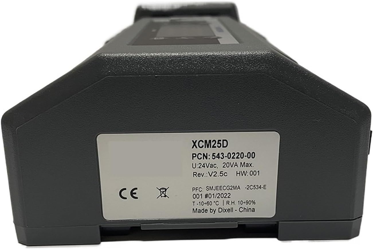
Figure 3.2: Side view of the ZDJKOPCVR Unit Controller XCM25D, featuring a white product label. The label displays important information such as "XCM25D", "PCN: 543-0220-00", "U:24Vac, 20VA Max.", "Rev:V2.5c", "HW:001", "T:-10-60°C", "R.H. 10-90%", and "Made by Dixell - China".
4. Operating Instructions
4.1 Basic Operation
- Power On/Off: Apply or remove power to the unit. The display will illuminate upon power-up.
- Display Reading: The main digital display shows the current measured temperature or other selected parameters.
- Start Button: Press the Start button to initiate or stop the control process.
- SET Button: Press the SET button to enter parameter setting mode or confirm a selection.
- Up/Down Arrows: Use the Up (▲) and Down (▼) arrow buttons to navigate through menus or adjust parameter values.
4.2 Parameter Settings
To adjust control parameters such as setpoint, differential, or alarm thresholds:
- Press and hold the SET button until the parameter code appears.
- Use the Up and Down arrows to select the desired parameter.
- Press SET again to view the current value.
- Use the Up and Down arrows to modify the value.
- Press SET to confirm and save the new value.
- To exit parameter setting mode, wait for a timeout or press the SET button repeatedly until the main display returns.
Refer to the detailed parameter list in the full technical manual for specific parameter codes and their functions.
5. Maintenance
5.1 Cleaning
- Disconnect power before cleaning.
- Wipe the exterior of the controller with a soft, damp cloth. Do not use abrasive cleaners, solvents, or excessive moisture.
- Ensure no liquid enters the unit.
5.2 Environmental Checks
- Periodically inspect the installation environment to ensure it remains within the specified operating conditions (temperature, humidity).
- Check for any signs of dust accumulation, corrosion, or loose connections.
6. Troubleshooting
This section provides solutions to common issues. For problems not listed here, contact technical support.
| Problem | Possible Cause | Solution |
|---|---|---|
| Controller does not power on. | No power supply or incorrect wiring. | Check power connections and ensure the 24Vac supply is active. Verify wiring according to Section 3.2. |
| Display shows "Err" or an error code. | Sensor fault, out-of-range reading, or internal error. | Check sensor connections and ensure the sensor is functioning correctly. Refer to the full technical manual for specific error code meanings. |
| Temperature reading is inaccurate. | Faulty sensor, incorrect sensor type setting, or sensor placement. | Verify sensor type and calibration. Ensure the sensor is correctly positioned and not damaged. |
| Output not activating/deactivating. | Incorrect setpoint, differential settings, or faulty output wiring. | Check setpoint and control parameters. Verify output wiring and the functionality of the connected device. |
7. Specifications
| Parameter | Value |
|---|---|
| Model | XCM25D |
| Part Number (PCN) | 543-0220-00 |
| Input Voltage (U) | 24Vac |
| Max Power Consumption | 20VA Max |
| Revision (Rev) | V2.5c |
| Hardware Version (HW) | 001 |
| Operating Temperature (T) | -10 to 60°C |
| Relative Humidity (R.H.) | 10-90% (non-condensing) |
| Manufacturer | Made by Dixell - China |
8. Warranty and Support
Warranty information for the ZDJKOPCVR Unit Controller XCM25D is not included in this document. For details regarding warranty coverage, technical support, or service, please contact your supplier or the manufacturer directly.
When contacting support, please have your product model (XCM25D) and any relevant serial numbers or purchase information available.