1. Introduction
This manual provides essential information for the safe and efficient operation of your VECTOR WELDING MIG MAG 200A Welder. Please read these instructions thoroughly before operating the equipment to ensure proper use, prevent injury, and maintain product longevity. Keep this manual for future reference.
1.1 Safety Information
Welding operations involve inherent risks. Always wear appropriate personal protective equipment (PPE), including a welding helmet, gloves, and protective clothing. Ensure adequate ventilation in your workspace. Disconnect power before performing any maintenance or adjustments. Consult local safety regulations for additional guidelines.

Figure 1: The VECTOR WELDING MIG MAG 200A Welder and its primary accessories, including a welding helmet, ground clamp, electrode holder, MIG torch, and welding wire spools.
2. Product Overview
2.1 Included Components
The VECTOR WELDING MIG MAG 200A Welder package typically includes:
- 1 x MIG MAG 200A Welding Machine
- 1 x AK-14 Tubular Wire Torch, 2m length
- 1 x Ground Clamp with 2m cable
- 1 x Electrode Holder with 2m cable
- 1 x Roll of 0.5 kg Flux-cored Wire (NoGas, 1.0 mm)
- 1 x Roll of 0.5 kg Welding Wire (with 1.0 mm gas protection)
- 1 x Hammer Brush
- 1 x Welder's Helmet

Figure 2: Overview of the welder's dimensions (375mm x 158mm x 200mm) and the standard accessories provided with the unit. The unit weighs 8kg.
2.2 Control Panel and Connections
The welder features a high-resolution digital display and a 3-button control system for ease of use. Familiarize yourself with the panel layout:
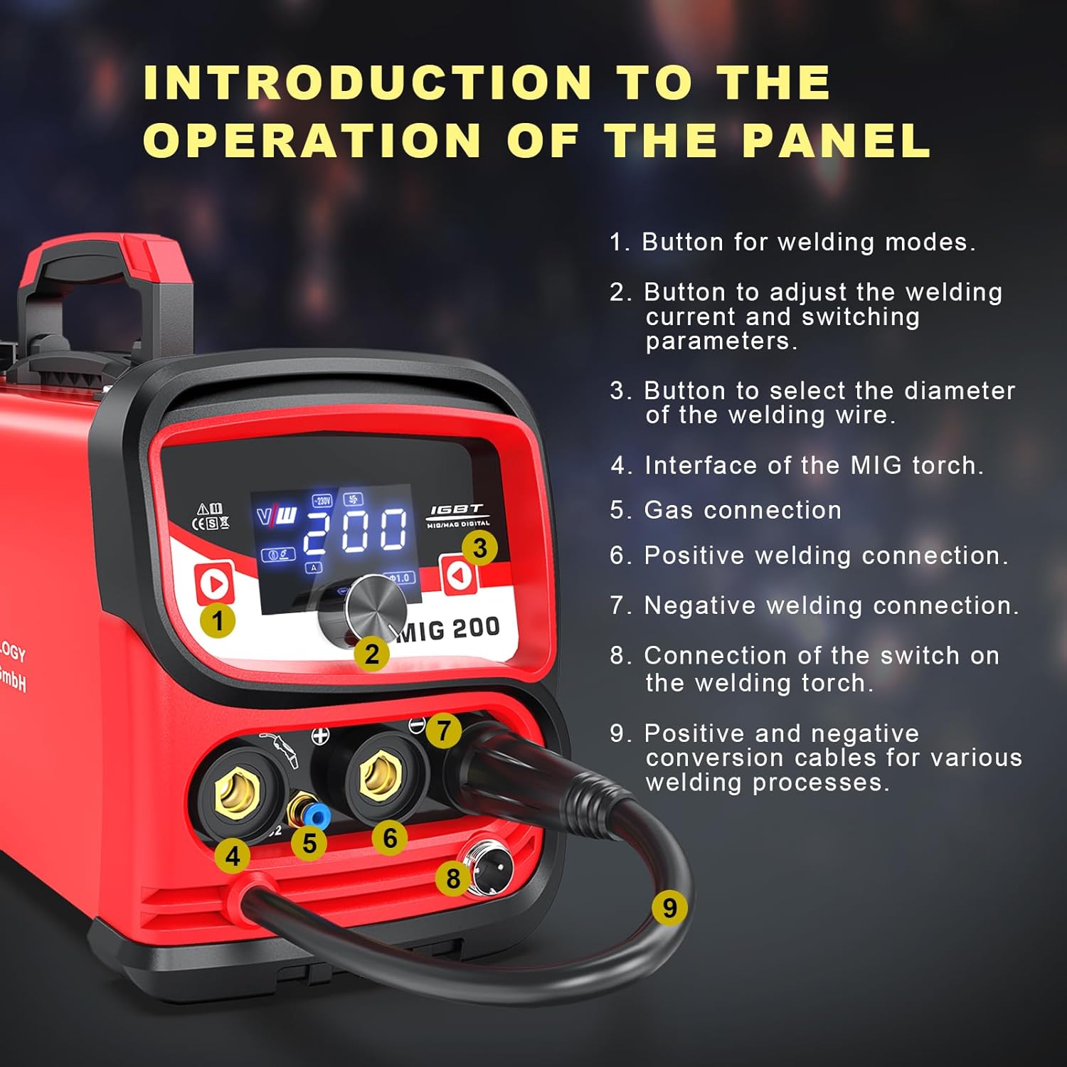
Figure 3: Front panel layout. Key components include (1) Welding mode button, (2) Welding current/parameter adjustment button, (3) Wire diameter selection button, (4) MIG torch interface, (5) Gas connection, (6) Positive welding connection, (7) Negative welding connection, (8) Welding torch switch connection, and (9) Positive and negative conversion cables.

Figure 4: The LED digital screen displays welding mode, current, voltage, and selected wire diameter. Welding in 3 steps: 1. Select the welding mode, 2. Adjust the welding current, 3. Select the wire diameter.
3. Setup
3.1 Power Connection
Connect the welder to a 230V power supply. Ensure the power source is capable of handling the welder's maximum input current (30.9A) to prevent overload.
3.2 Wire Spool Installation
Open the side panel of the welder to access the wire feed mechanism. Install the appropriate welding wire spool (0.5kg or 1kg) onto the shaft, securing it with the coil spacer, spring, and spool lock. Ensure the wire feeds smoothly through the guide.

Figure 5: Internal view of the wire feed mechanism, showing the spool, shaft, coil spacer, spring, and spool lock. The applicable outer diameter of the spool is 100 mm. Wire diameters supported are 0.8/1.0 mm. Welding thickness range is 0.5 - 5 mm.
3.3 Connecting Welding Cables and Torch
- MIG Torch: Connect the MIG torch to the MIG torch interface (4) on the front panel.
- Ground Clamp: Connect the ground clamp to the negative welding connection (7). Attach the clamp securely to the workpiece.
- Electrode Holder (for MMA): Connect the electrode holder to the positive welding connection (6).
- Gas Connection (for MIG with gas): If using solid wire with gas protection, connect your gas cylinder and regulator to the gas connection (5).
- Torch Switch: Connect the welding torch switch to its designated connection point (8).
4. Operating Instructions
The VECTOR WELDING MIG MAG 200A Welder supports multiple welding processes: MIG (with/without gas), LIFT TIG, and MMA (ARC).

Figure 6: The welder supports MIG with gas, MIG without gas (flux-cored), Lift TIG, and ARC/MMA welding processes.
4.1 General Operation Steps
- Select Welding Mode: Press button (1) on the control panel to cycle through MIG (with gas), MIG (without gas), LIFT TIG, and MMA modes.
- Adjust Welding Current: Use button (2) to adjust the welding current (30-200A for MIG, 30-170A for ARC, 10-200A for TIG) and other parameters as needed for your material and thickness.
- Select Wire Diameter (MIG): For MIG welding, use button (3) to select the correct wire diameter (0.8mm or 1.0mm) to match your installed wire.
- Begin Welding: Once settings are configured and safety precautions are observed, you can begin your welding task.
4.2 Welding Processes
- MIG Welding (Gas/No-Gas): This process is suitable for various materials including aluminum, magnesium, carbon steel, and alloy steels. The machine provides stable arc performance with minimal spatter due to its advanced IGBT inverter technology.
- LIFT TIG Welding: For precise welding tasks, the LIFT TIG function offers controlled arc initiation.
- MMA (ARC) Welding: Use the electrode holder for stick welding applications.
The welder is designed for versatility, making it suitable for DIY projects, domestic repairs, industrial applications, and vehicle maintenance.
5. Maintenance
Regular maintenance ensures the longevity and optimal performance of your welding machine. Always disconnect the welder from the power supply before performing any maintenance.
- Cleaning: Periodically clean the exterior of the machine with a dry cloth. Use compressed air to clear dust and debris from ventilation openings.
- Cable Inspection: Regularly inspect all welding cables, connections, and the torch for signs of wear, damage, or loose connections. Replace damaged components immediately.
- Wire Feed Mechanism: Keep the wire feed rollers clean and free of debris to ensure smooth wire feeding.
- Consumables: Replace worn contact tips, nozzles, and electrodes as needed.
6. Troubleshooting
If you encounter issues with your welder, consider the following general troubleshooting steps:
- No Power: Check the power cord connection, circuit breaker, and ensure the power switch on the welder is in the 'ON' position.
- No Arc: Verify all welding cable connections (ground clamp, electrode holder/MIG torch). Ensure the workpiece is clean and provides good electrical contact. Check for correct welding mode and parameter settings.
- Poor Weld Quality: Adjust welding current/voltage, wire feed speed (for MIG), and ensure proper wire diameter selection. Check for contaminated base material or incorrect gas flow (if applicable).
- Overheating: If the welder shuts off due to overheating, allow it to cool down. Ensure ventilation openings are clear and the duty cycle is not exceeded.
For persistent issues, contact VECTOR WELDING customer support.
7. Specifications
Technical specifications for the VECTOR WELDING MIG MAG 200A Welder (Model: MIG200 SET):
| Feature | Specification |
|---|---|
| Weight | 8 kg |
| Dimensions (L x W x H) | 375mm x 158mm x 200mm |
| Cooling | Fan Cooled |
| Welder Type | Inverter Welder |
| European Standards | EN 60974-1 / IEC 60974-1 |
| Mains Voltage | 1 x 230 Volt ±15% |
| Mains Frequency | 50/60Hz |
| Spool Weight Capacity | 0.5kg / 1kg |
| Wire Diameter | Φ0.8 / Φ1.0 mm |
| Efficiency | 80% |
| Power Factor | 0.8 |
| MIG Welding Current Range | 30-200A |
| ARC Welding Current Range | 30-170A |
| TIG Welding Current Range | 10-200A |
| Effective Input Current | 16.8 A |
| Maximum Input Current | 30.9 A |
| Single-phase Generators | 10KVA |
| Duty Cycle (ED) 40°C (MIG) | 200A @ 40% 24V, 126A @ 100% 15V |
| Duty Cycle (ED) 40°C (ARC) | 170A @ 30% 26.8V, 93A @ 100% 23.7V |
| Duty Cycle (ED) 40°C (TIG) | 200A @ 40% 18V, 126A @ 100% 15V |
| Open Circuit Voltage | 60V DC |
| Protection Degree | IP23 |
| Insulation Class | H |
8. Warranty and Support
For warranty information, technical support, or spare parts inquiries, please contact VECTOR WELDING GmbH directly. Refer to your purchase documentation for specific warranty terms and contact details.
Manufacturer: VECTOR WELDING GmbH