1. Introduction
This manual provides detailed instructions for the safe and effective use of your Proster Electrical Tools Set, which includes a 6000 Count Clamp Meter and a Non-Contact Voltage Tester Pen. Please read this manual thoroughly before operation and retain it for future reference.
2. Safety Information
WARNING: Electrical testing can be hazardous. Always exercise extreme caution and follow all safety guidelines to prevent electric shock or injury.
- Always verify the absence of voltage before touching any circuit.
- Do not use the devices if they appear damaged or are operating abnormally.
- Ensure proper battery installation and replacement.
- Wear appropriate personal protective equipment (PPE), such as insulated gloves and safety glasses.
- Do not exceed the maximum input values specified for each function.
- Keep hands and fingers away from the probe tips when testing live circuits.
3. Package Contents
Your Proster Electrical Tools Set (Model PST088c-PST224) includes:
- Proster 6000 Count Clamp Meter
- Proster Non-Contact Voltage Tester Pen
- Test Leads (Red and Black)
- K-Type Thermocouple (for temperature measurement)
- Carrying Pouch
- AAA Batteries (for Voltage Tester Pen)
- User Manuals
4. Clamp Meter Overview
The Proster 6000 Count Clamp Meter is a versatile tool for measuring various electrical parameters. Familiarize yourself with its components:

Figure 1: Proster Clamp Meter with its auto-ranging control dial and function buttons.
- Clamp Jaw: For non-contact AC/DC current measurement.
- Function Dial: Selects measurement modes (NCV, AC/DC Current, AC/DC Voltage, Resistance/Capacitance/Diode/Continuity, Frequency, Temperature).
- SELECT/ID Button: Toggles between functions within a dial setting (e.g., AC/DC voltage, resistance/diode/continuity/capacitance). Also activates flashlight.
- RANGE/HOLD Button: Toggles auto-ranging or manual range selection. Long press activates data hold and backlight.
- Hz/DUTY Button: Selects frequency or duty cycle measurement.
- LCD Display: Shows measurement readings, units, and indicators.
- Input Jacks: For connecting test leads and thermocouple.
5. Non-Contact Voltage Tester Pen Overview
The Non-Contact Voltage Tester Pen provides a safe and convenient way to detect AC voltage.

Figure 2: Proster Non-Contact Voltage Tester Pen, highlighting its compact design and integrated flashlight.
- Probe Tip: Detects AC voltage without direct contact.
- Power Button: Turns the device on/off.
- Sensitivity Adjustment Button: Toggles between high, medium, and low sensitivity modes. Long press activates the LED flashlight.
- LED Indicators: Visual indication of voltage presence and sensitivity level.
- Buzzer: Audible alarm for voltage detection.
6. Setup
6.1. Battery Installation
Both devices require batteries for operation. Ensure correct polarity during installation.
Clamp Meter:
The clamp meter typically uses 9V batteries. Refer to the battery compartment cover on the back of the device for specific instructions and battery type.
Non-Contact Voltage Tester Pen:
The voltage tester pen uses 2 x 1.5V AAA batteries. Unscrew the cap at the bottom of the pen to access the battery compartment. Insert the batteries according to the polarity markings and re-secure the cap.
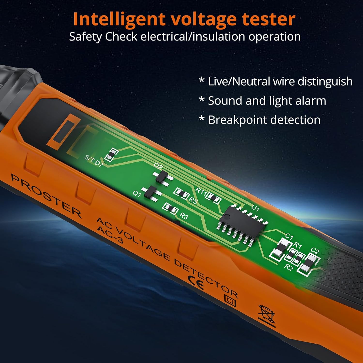
Figure 3: Internal view of the Voltage Tester Pen, illustrating its intelligent design for safety checks.
7. Operating the Clamp Meter
Turn the function dial to the desired measurement mode. The meter features auto-ranging, automatically selecting the appropriate range for most measurements.
7.1. Measuring AC/DC Current (Clamp)
- Turn the function dial to the 'A~' (AC Current) or 'A=' (DC Current) position.
- Open the clamp jaw and enclose a single conductor. Ensure the jaw is fully closed.
- Read the current value on the LCD display.
Video 1: Official Proster video demonstrating the Clamp Multimeter with True RMS, including current measurement.
7.2. Measuring AC/DC Voltage (Leads)
- Insert the red test lead into the 'VΩ' jack and the black test lead into the 'COM' jack.
- Turn the function dial to the 'V~' (AC Voltage) or 'V=' (DC Voltage) position. Use the SELECT button to toggle if needed.
- Connect the test probes to the circuit points you wish to measure.
- Read the voltage value on the LCD display.

Figure 4: Measuring DC voltage using the test leads connected to the clamp meter.
7.3. Measuring Resistance, Capacitance, Diode, Continuity
- Insert the red test lead into the 'VΩ' jack and the black test lead into the 'COM' jack.
- Turn the function dial to the 'Ω' (Resistance/Diode/Continuity/Capacitance) position.
- Use the SELECT button to cycle through Resistance (Ω), Diode, Continuity, and Capacitance (F) modes.
- Connect the test probes to the component under test. For continuity, a buzzer will sound if resistance is low.
7.4. Measuring Frequency (Hz)
- Insert the red test lead into the 'VΩ' jack and the black test lead into the 'COM' jack.
- Turn the function dial to the 'Hz' position.
- Connect the test probes to the circuit.
- Read the frequency value on the LCD display.
7.5. Measuring Temperature (°C/°F)
- Insert the K-type thermocouple into the input jacks, observing polarity.
- Turn the function dial to the '°C/°F' position.
- Place the thermocouple tip on or in the object whose temperature you wish to measure.
- Read the temperature on the LCD display. Use the SELECT button to switch between Celsius and Fahrenheit.
7.6. Non-Contact Voltage (NCV) Detection
- Turn the function dial to the 'NCV' position.
- Move the top of the clamp meter near the conductor or circuit.
- The meter will beep and the NCV indicator will light up if AC voltage is detected.

Figure 5: NCV function of the clamp meter detecting voltage near an electrical outlet.
7.7. Data Hold and Backlight
- Data Hold: Press the 'HOLD' button briefly to freeze the current reading on the display. Press again to release.
- Backlight: Long press the 'HOLD' button to turn the display backlight on or off, useful in low-light conditions.
8. Operating the Non-Contact Voltage Tester Pen
This pen-style tester is designed for quick and safe voltage checks.
Video 2: Official Proster video demonstrating the Non-Contact Voltage Tester Pen's features and operation.
8.1. Power On/Off
Press the green power button to turn the tester on. The green LED will illuminate. Press and hold the power button to turn it off.
8.2. Adjusting Sensitivity
The default AC voltage detection range is 48-1000V. You can adjust the sensitivity to measure 12-1000V.
- Short press the sensitivity adjustment button (marked 'S') to cycle through high, medium, and low sensitivity modes.
- The LED indicators will change to reflect the selected sensitivity.
8.3. Live/Null Wire Distinction
When the probe tip is near a live wire, the tester will beep rapidly and the red LED will flash quickly. For a null wire, the buzzer will alarm slowly, and the green LED will flash slowly.

Figure 6: The voltage tester pen indicating null wire (slow beep, green flash) and live wire (fast beep, red flash).
8.4. Flashlight Function
Long press the sensitivity adjustment button ('S') to turn the built-in LED flashlight on or off. This is useful for working in dimly lit areas.
Figure 7: The integrated LED flashlight on the voltage tester pen assists in dark environments.
8.5. Breakpoint Detection
The tester can help locate breakpoints in wires. Move the probe along the wire; the alarm will stop at the point where the circuit is interrupted.

Figure 8: Breakpoint detection feature of the voltage tester pen.
9. Maintenance
9.1. Cleaning
Wipe the devices with a dry, clean cloth. Do not use abrasive cleaners or solvents. Ensure the devices are dry before storage.
9.2. Battery Replacement
Replace batteries promptly when the low battery indicator appears on the display. Refer to section 6.1 for battery installation instructions.
9.3. Storage
Store the tools in their carrying pouch in a cool, dry place, away from direct sunlight and extreme temperatures. Remove batteries if the devices will not be used for an extended period.
10. Troubleshooting
- Device does not power on: Check battery installation and ensure batteries are not depleted. Replace if necessary.
- Inaccurate readings: Ensure test leads are properly connected and the correct function is selected on the dial. For clamp meter, ensure only one conductor is within the jaw for current measurement.
- NCV tester constantly beeping/false positives: Adjust sensitivity to a lower setting. High sensitivity can pick up interference from nearby electrical fields.
- "EF" error on Clamp Meter: This typically indicates an overload or out-of-range condition. Ensure the measurement is within the device's specified limits.
11. Specifications
| Feature | Specification |
|---|---|
| Brand | Proster |
| Model | PST088c-PST224 |
| Power Source | Battery Powered |
| Color | Orange |
| Safety Standard | UL 61010-1, IEC 61010-2-030 |
| Upper Temperature Rating | 1000 Degrees Celsius |
| Clamp Meter Display Count | 6000 Counts |
| NCV Detection Range (Default) | 48-1000V AC |
| NCV Detection Range (Adjustable) | 12-1000V AC |
| Clamp Jaw Opening Size | Up to 28mm |
12. Warranty and Support
Proster products are designed for reliability and performance. For warranty information, technical support, or service inquiries, please refer to the contact details provided on the product packaging or visit the official Proster website. Keep your purchase receipt as proof of purchase.