1. Introduction
This manual provides essential information for the safe and effective operation of the DEWIN GYAR9-AC-G Intelligent Automatic Reclosing RCCB Circuit Breaker. This device is designed to automatically reclose the circuit breaker in the event of an unexpected trip, minimizing downtime and maintenance efforts. It features a digital display for operational status and a robust design for various applications.
Please read this manual thoroughly before installation and operation to ensure proper usage and to prevent potential hazards.

Image 1.1.1: Front and side view of the DEWIN GYAR9-AC-G Intelligent Automatic Reclosing RCCB Circuit Breaker, showing its compact design and digital display.
2. Safety Information
WARNING: Installation and maintenance of this device must only be performed by qualified professionals. Non-professionals are not permitted to install this device due to the risk of electric shock and other hazards.
- Always disconnect power before installing, wiring, or performing any maintenance on the circuit breaker.
- Ensure all wiring connections are secure and comply with local electrical codes and standards.
- Do not operate the device if it appears damaged or malfunctioning.
- This device is not suitable for photovoltaic systems installed by individuals.
- The "LOCK" mechanism is a safety feature. Do not attempt to bypass it.
3. Product Overview
3.1 Key Features
- Intelligent automatic reclosing functionality.
- Durable PC material construction with IP20 protection grade.
- Standard DIN rail installation (35 mm).
- 3-digit digital display for operational status and countdown.
- Two switching modes: Automatic (AUTO) and Manual (MANU).
- LED indicator for clear status indication (Green for normal, Red for fault).
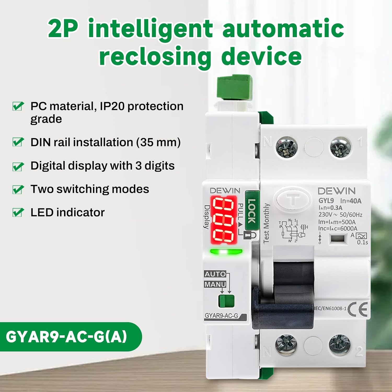
Image 3.1.1: Visual summary of key features including PC material, IP20 protection, DIN rail installation, digital display, two switching modes, and LED indicator.
3.2 Product Components
The following image identifies the main components of the DEWIN GYAR9-AC-G circuit breaker:

Image 3.2.1: Overview of the DEWIN GYAR9-AC-G circuit breaker, highlighting the leakage switch, safety lock, broken code display, LED digital display, working mode selection switch, and operating handle.
- Leakage Switch: Detects current leakage and trips the circuit.
- Safety Lock ("LOCK"): Prevents accidental closing of the circuit breaker when engaged.
- Broken Code Display: The 3-digit digital display shows the number of opening and closing operations and the countdown for reclosing.
- LED Digital Display: Provides visual status feedback.
- Working Mode Selection: Switch between AUTO (automatic reclosing) and MANU (manual operation).
- Operating Handle: Used for manual opening and closing of the circuit.
- Product Number: GYAR9-AC-G, located on the device.
4. Specifications
The following table details the technical specifications of the DEWIN GYAR9-AC-G Intelligent Automatic Reclosing RCCB Circuit Breaker:
| Parameter | Value |
|---|---|
| Material | Polycarbonate |
| Supply Voltage | 230V AC |
| Rated Current | 40A |
| Operating Frequency | 50/60 Hz |
| Leakage Protection | 300mA |
| Control Signal | Automatic reclosing + dry contact control |
| Digital Display | 3-digit (trips, closures, countdown) |
| Effective Control Signal Duration | > 400 ms |
| Closing Action Time | < 1 s |
| Opening Action Time | < 0.5 s |
| Control Cable Length | ≤ 1500 m |
| Power Consumption (Static) | ≤ 1.5 VA |
| Power Consumption (Dynamic) | ≤ 25 VA |
| Rated Insulation Voltage | 400 V |
| Rated Impulse Withstand Voltage (Uimp) | 4 kV |
| Electrical Life | 10,000 movements (3 movements/minute) |
| Mechanical Life | 10,000 cycles |
| Protection Rating | IP20 |
| Ambient Temperature | -25 °C to +70 °C |
| Storage Temperature | -40 °C to +70 °C |
| Terminal Capacity (Power/Control) | 28-12 AWG, 2.5 mm² |
| Terminal Capacity (Auxiliary Signal) | 28-14 AWG, 1.5 mm² |
| Mounting | DIN rail EN 60715 (35mm) |
| Dimensions (L x W x H) | 1 x 1 x 1 cm |
| Weight | 358 grams |
| Model Number | RCBAACBYR-GS99739 |
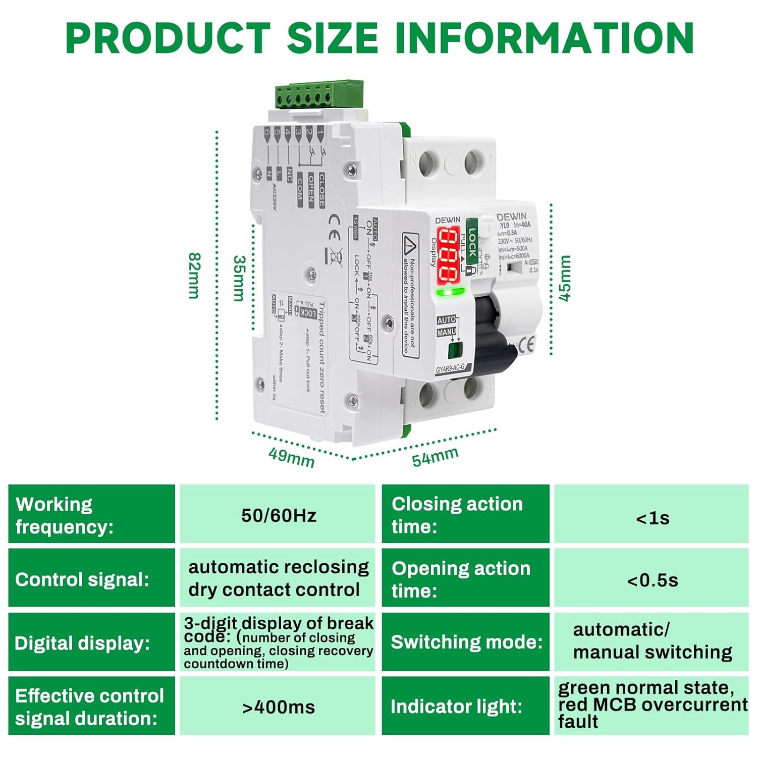
Image 4.1.1: Visual representation of product dimensions and a summary of key specifications including working frequency, control signal, digital display, closing action time, opening action time, switching mode, and indicator light.
4.2 Waveform Definition
The device is designed to operate with specific AC and A-type waveforms. Refer to the table below for details:

Image 4.2.1: Table detailing waveform definitions and their action ranges for Sinusoidal AC, Pulsating DC, High Frequency, Two-phase full-wave rectification, Three-phase full-wave rectification, and DC currents.
5. Installation
Installation must be performed by a qualified electrician in accordance with all applicable national and local electrical codes. Ensure the main power supply is disconnected before beginning installation.
5.1 Wiring Diagram
The following diagram illustrates the typical wiring for the DEWIN GYAR9-AC-G circuit breaker:

Image 5.1.1: Wiring diagram showing connections for Line (L), Neutral (N), and auxiliary control signals (Opening button, Closing button). The diagram also illustrates connection to downstream Miniature Circuit Breakers (MCBs) and loads.
Important Notes for Wiring:
- The product does not require an external button for automatic reclosing.
- When manually controlling the opening and closing of the switch, an external control button is required.
- If a normally open self-reset button is used, other button types are not applicable.
5.2 Terminal Connections
Ensure proper and secure connection of all wires to the terminal block. Refer to the wiring diagram for correct terminal assignments.

Image 5.2.1: Close-up view of the terminal block, showing the screw terminals for secure wire connections.
5.3 DIN Rail Mounting
The device is designed for mounting on a standard 35mm DIN rail (EN 60715). Ensure it is securely fastened to prevent movement.
6. Operation
6.1 Switching Modes (AUTO/MANU)
The circuit breaker offers two operational modes, selected via the AUTO/MANU switch on the front panel:
- AUTO Mode: In this mode, the circuit breaker will automatically attempt to reclose after a fault. This reduces the need for manual intervention and minimizes downtime.
- MANU Mode: In this mode, manual reclosing is required after a fault. The automatic reclosing function is disabled.
When the "LOCK" mechanism is engaged (pulled up), the circuit breaker cannot be closed, ensuring electrical safety and preventing accidental contact.
6.2 LED Indicator and Digital Display
The device features an LED indicator and a 3-digit digital display to communicate its status:
| Mode | LED Digital Display Indication |
|---|---|
| In AUTO mode | Red flashing indicates opening (fault state). Green flashing indicates closing (normal operation). The digital display shows the number of opening and closing operations and the countdown time for reclosing recovery. |
| In MANU mode | Yellow light is always on for manual opening and closing. The digital display shows the number of opening and closing operations and the countdown time for reclosing recovery. |
Note: The digital display does not show voltage.
6.3 Self-Locking Mode
To ensure safety, the device enters a self-locking mode after multiple reclosing failures:
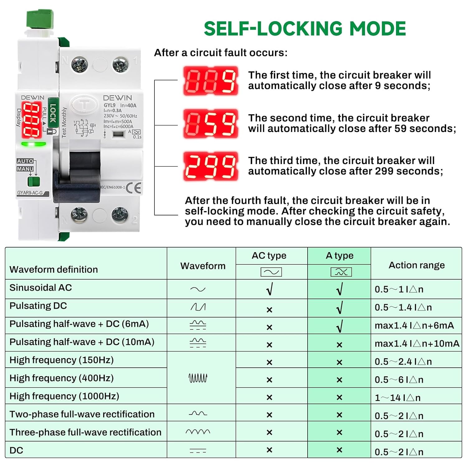
Image 6.3.1: Illustration of the self-locking sequence, showing reclosing attempts at 9, 59, and 299 seconds, followed by self-locking after the fourth fault.
- First Fault: The circuit breaker automatically recloses after 9 seconds.
- Second Fault: The circuit breaker automatically recloses after 59 seconds.
- Third Fault: The circuit breaker automatically recloses after 299 seconds.
- Fourth Fault: After the fourth consecutive fault, the circuit breaker enters self-locking mode. It will not reclose automatically. Manual intervention is required after checking the circuit safety.
7. Maintenance
Regular maintenance helps ensure the longevity and reliable operation of your DEWIN circuit breaker.
- Visual Inspection: Periodically inspect the device for any signs of physical damage, loose connections, or discoloration.
- Cleaning: Keep the device clean and free from dust and debris. Use a dry, soft cloth for cleaning. Do not use liquid cleaners.
- Function Test: It is recommended to periodically test the leakage protection function using the "Test Monthly" button on the device, following safety guidelines.
- Professional Check: For any complex issues or concerns, consult a qualified electrician.
8. Troubleshooting
8.1 Circuit Breaker in Self-Locking Mode
If the circuit breaker enters self-locking mode after multiple faults, it will remain open until manually reset. This indicates a persistent issue in the circuit that requires investigation.
Reset Procedure for Self-Locking Mode (and Trip Count Reset):
This procedure also resets the trip counter on the digital display to zero.
- Ensure the circuit breaker is in AUTO mode.
- Switch the mode selector to MANU.
- Manually trip the circuit breaker using the lever or test button.
- Pull up the LOCK (green) mechanism to engage the safety lock. Wait until any internal humming sound stops, indicating the switching process is complete.
- Quickly switch the mode selector from MANU to AUTO and back to MANU twice in rapid succession.
- The digital display should now show "0".
- Ensure the mode selector is in MANU.
- Push down the LOCK (green) mechanism to disengage the safety lock. Wait until any internal humming sound stops.
- Manually close the circuit breaker by pushing the lever up.
- Switch the mode selector back to AUTO.
If the circuit breaker continues to trip after resetting, a professional electrician should inspect the electrical system to identify and resolve the underlying fault.
9. Application
The DEWIN GYAR9-AC-G Intelligent Automatic Reclosing RCCB Circuit Breaker is suitable for a variety of applications where reliable circuit protection and automatic fault recovery are beneficial:
- Unmanned mobile phone base stations.
- Elevators.
- Smart homes and smart factories.
- New energy vehicle charging piles.
- Photovoltaic grid-connected AC distribution boxes.
Important: This device cannot be used for photovoltaic systems installed by individuals.
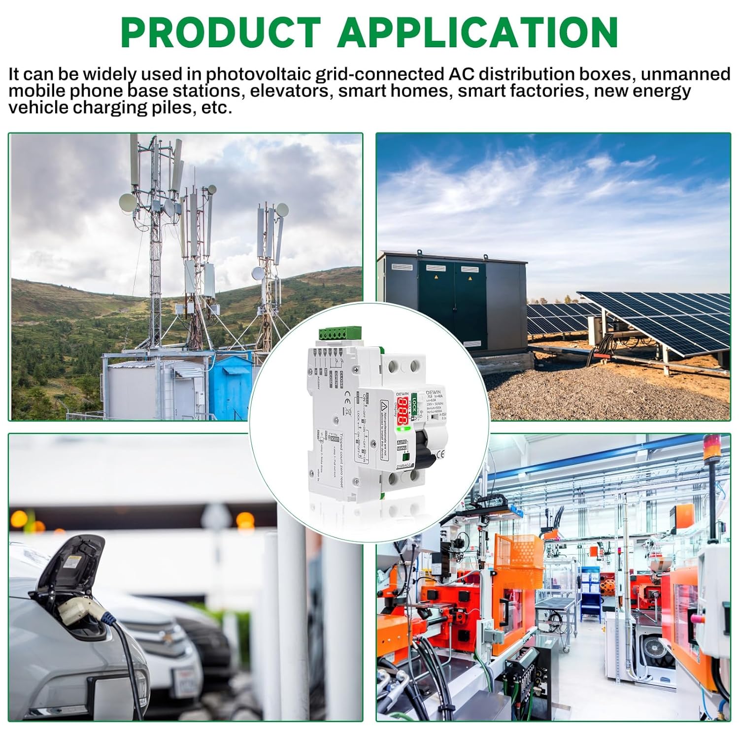
Image 9.1.1: Examples of typical applications for the DEWIN circuit breaker, including mobile base stations, smart factories, and EV charging stations.
10. Warranty and Support
For warranty information, technical support, or service inquiries, please refer to the documentation provided with your purchase or contact DEWIN customer service directly. Keep your purchase receipt as proof of purchase.