1. Introduction
This manual provides essential instructions for the safe and effective assembly, operation, and maintenance of your SBPKMARSCT 750Lbs Lawn Mower Lift. Please read this manual thoroughly before using the product to ensure proper function and safety.
The SBPKMARSCT Lawn Mower Lift is constructed from Q235 carbon steel, designed for durability and resistance to impact and rust. It features a powerful lifting mechanism capable of raising lawn mowers up to 24.41 inches, facilitating tasks such as blade replacement, debris cleaning, and general maintenance. The adjustable wheel span (0-9.84 inches) ensures compatibility with a wide range of garden tractors, lawnmowers, ATVs, and push mowers. With a strong load-bearing capacity of up to 750 lbs, this lift provides a secure platform for your equipment maintenance needs.
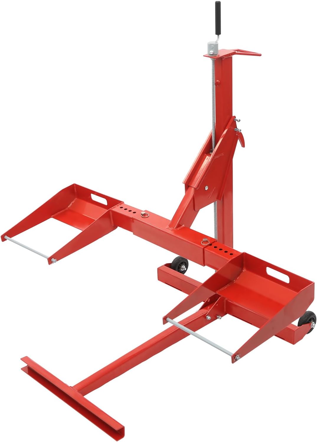
Figure 1.1: Fully assembled SBPKMARSCT 750Lbs Lawn Mower Lift.
2. Safety Information
Always prioritize safety when operating the lawn mower lift. Failure to follow these instructions may result in serious injury or property damage.
- Read the Manual: Read and understand the entire instruction manual before operating the lift.
- Weight Capacity: Do not exceed the maximum load capacity of 750 lbs (340 kg).
- Stable Surface: Always operate the lift on a hard, level, and solid surface. Avoid uneven ground or soft surfaces.
- Secure the Mower: Ensure the lawn mower is properly centered and secured with the provided straps before lifting.
- Safety Lock: Always engage the safety locking mechanism once the mower is lifted to the desired height. Never work under a mower supported only by the hydraulic jack.
- Personal Protective Equipment (PPE): Wear appropriate safety gear, including safety glasses and gloves.
- Clear Area: Keep hands, feet, and other body parts clear of moving parts and pinch points during operation.
- Children and Pets: Keep children and pets away from the work area.
- Inspection: Inspect the lift for any damage or wear before each use. Do not use if damaged.
3. Parts List
Verify that all components are present before beginning assembly.
- 1x Lawn Mower Lift Frame
- 1x Hydraulic Jack
- 2x Wheel Pads
- 2x Safety Straps
- Various bolts, nuts, washers, and pins for assembly
- Other accessories for assembly (e.g., wrench, allen key)

Figure 3.1: All components included in the package.
4. Setup and Assembly
Follow these steps to assemble your lawn mower lift. Refer to the assembly video for visual guidance.
- Unpack all components and verify against the parts list.
- Attach the main frame components using the provided bolts and nuts. Ensure all connections are secure.
- Install the hydraulic jack into its designated position within the frame.
- Attach the wheel pads to the adjustable arms. These can be adjusted later to fit your mower's wheel span.
- Insert all necessary pins and secure them with cotter pins or clips.
Video 4.1: Detailed product assembly instructions.
This video demonstrates the step-by-step process of assembling the lawn mower lift, including attaching frame components, installing the hydraulic jack, and securing all parts.
5. Operating Instructions
Follow these steps for safe and effective operation of your lawn mower lift.
5.1. Preparing the Mower and Lift
- Ensure the mower is turned off, the engine is cool, and the parking brake is engaged.
- Position the lift on a hard, level surface behind the mower's front wheels.
- Adjust the width of the lift's wheel pads to match the mower's front wheel span (0-9.84 inches).
- Carefully roll the mower onto the lift's wheel pads.
- Secure the mower's front wheels to the lift using the provided safety straps.
5.2. Lifting the Mower
- Insert the handle into the hydraulic jack's pump mechanism.
- Pump the handle to slowly raise the mower to the desired height. The lift can raise the mower up to 24.41 inches.
- Once at the desired height, engage the safety locking bar to secure the lift in place. Never work under the mower without the safety lock engaged.
- Place additional jack stands under the mower's frame for extra safety, if available.
Video 5.1: Demonstration of the lawn mower lift in use, showing the lifting process.
This video illustrates the process of positioning a mower on the lift, securing it, and raising it using the hydraulic mechanism. It highlights the safety features and the ease of access for maintenance.

Figure 5.1: Ample clearance for maintenance tasks under a lifted mower.
5.3. Lowering the Mower
- Ensure all tools and personnel are clear from under the mower.
- Remove any additional jack stands.
- To release the safety locking bar, pump the handle twice.
- Step down and hold the safety locking bar. Slowly turn the cylinder release valve 1/4 to 1/2 turn counter-clockwise to gradually lower the mower.
- Once fully lowered, release your foot from the safety locking bar.
- Remove the safety straps and carefully roll the mower off the lift.
6. Maintenance
Regular maintenance ensures the longevity and safe operation of your lawn mower lift.
- Cleaning: Keep the lift clean and free of dirt, grease, and debris. Wipe down with a damp cloth after each use.
- Lubrication: Periodically lubricate all pivot points and moving parts with a suitable lubricant to ensure smooth operation.
- Inspection: Regularly inspect all bolts, nuts, and pins for tightness. Check for any signs of wear, damage, or corrosion on the frame, hydraulic jack, and safety mechanisms. Replace any worn or damaged parts immediately.
- Hydraulic Fluid: Check the hydraulic fluid level periodically and refill if necessary, following the instructions for the specific hydraulic jack model.
7. Troubleshooting
If you encounter issues with your lawn mower lift, refer to the following common problems and solutions:
- Lift does not raise: Check if the hydraulic release valve is fully closed. Ensure there is sufficient hydraulic fluid.
- Lift lowers too quickly: The hydraulic release valve may be open too far. Turn it clockwise to tighten and control the descent speed. Check for hydraulic fluid leaks.
- Unstable lift: Ensure the lift is on a level, hard surface. Verify that the mower is centered and securely strapped. Check all bolts and connections for tightness.
- Difficulty engaging safety lock: Ensure the lift is raised to a position where the safety lock can fully engage.
If problems persist, contact customer support for assistance.
8. Specifications
| Feature | Specification |
|---|---|
| Brand | SBPKMARSCT |
| Model Number | GIYEDJ001 |
| Material | Q235 Carbon Steel |
| Load Capacity | 750 Pounds (340 kg) |
| Max Lift Height | 0-24.41 inches (0-62 cm) |
| Adjustable Wheel Span | 0-9.84 inches (0-25 cm) |
| Item Weight | 45 pounds (20.4 kg) |
| Package Dimensions | 43.31 x 17.72 x 7.87 inches (110 x 45 x 20 cm) |
| Lift Type | Manual Hydraulic |
9. Warranty and Support
For warranty information, technical support, or replacement parts, please contact SBPKMARSCT customer service through your original purchase channel. Keep your purchase receipt as proof of purchase.