1. Introduction
This manual provides essential information for the safe and effective installation, operation, and maintenance of the IMIFAFTAbT DC Motor Controller, specifically models 1520-5501, 1027745-01, and 1050752-01. This controller is designed for use with Curtis Club Car Golf Carts, operating at 48V with a 500A capacity. Please read this manual thoroughly before attempting any installation or operation to ensure proper function and safety.
2. Safety Information
Warning: Electrical components can be dangerous. Improper installation or handling can result in serious injury or damage to equipment. Always observe the following safety precautions:
- Disconnect all power sources before installing, servicing, or removing the controller.
- Ensure the golf cart is in a stable position and the parking brake is engaged.
- Wear appropriate personal protective equipment (PPE), including safety glasses and insulated gloves.
- Avoid touching live electrical terminals.
- Ensure all wiring connections are secure and correctly polarized.
- Consult a qualified technician if you are unsure about any part of the installation or troubleshooting process.
- Do not attempt to modify the controller.
3. Product Overview
The IMIFAFTAbT DC Motor Controller is a critical component for managing the power delivery to the motor in compatible Curtis Club Car Golf Carts. It ensures efficient and reliable operation of the vehicle's propulsion system. This controller is identified by part numbers 1520-5501, 1027745-01, and 1050752-01.
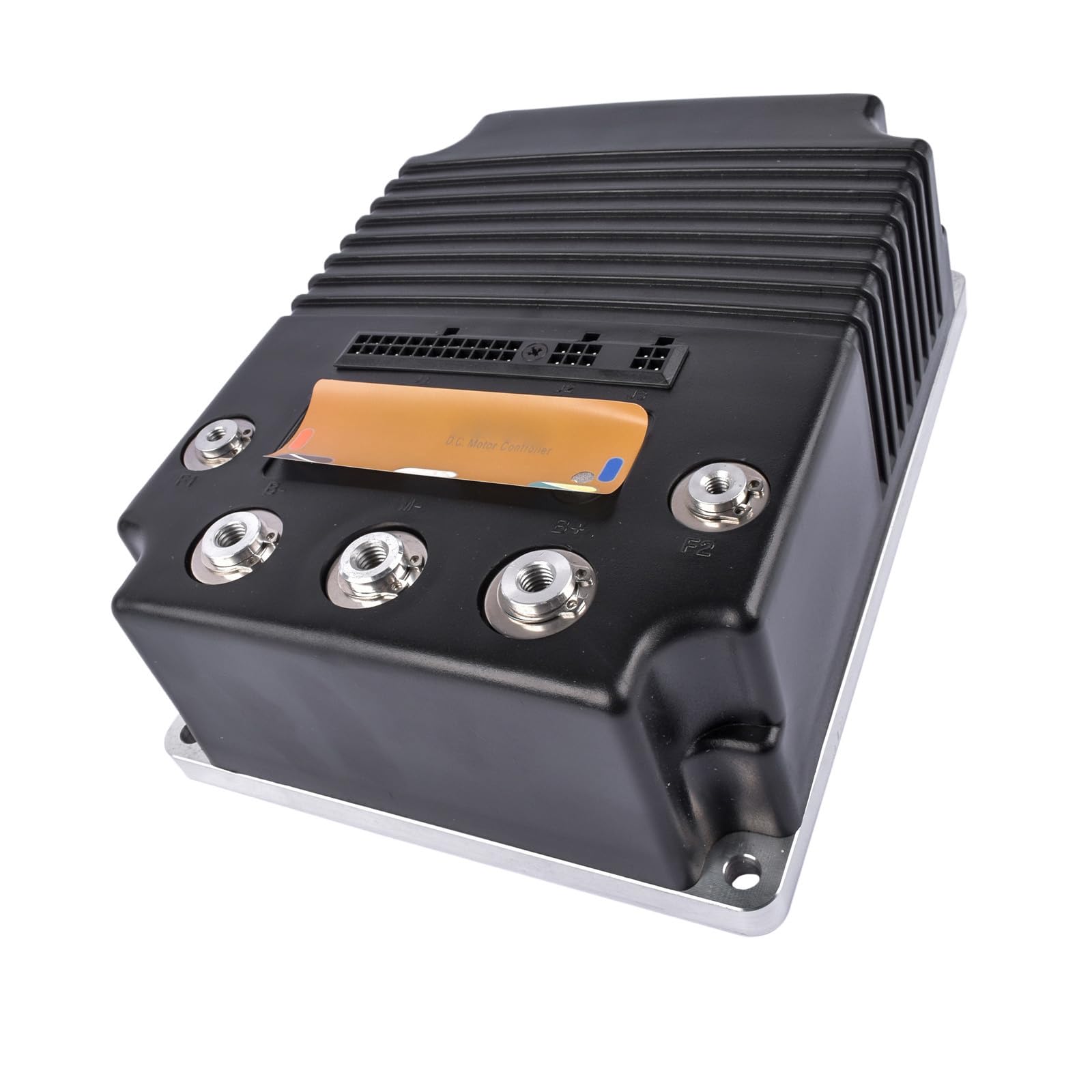
Figure 3.1: Top view of the IMIFAFTAbT DC Motor Controller. This image shows the main body of the controller with its heat sink fins and the primary connection points for power and control signals.

Figure 3.2: Angled view of the controller highlighting the various electrical connectors and terminals. The large terminals are for high-current connections, while the smaller multi-pin connectors are for control signals.

Figure 3.3: A different angled perspective of the DC motor controller, providing a clearer view of the terminal labels and the overall robust construction designed for vehicle applications.

Figure 3.4: Rear view of the controller, showing a label that typically contains model information, serial numbers, and possibly a "D.C. MOTOR CONTROLLER" designation, along with a warranty void sticker.
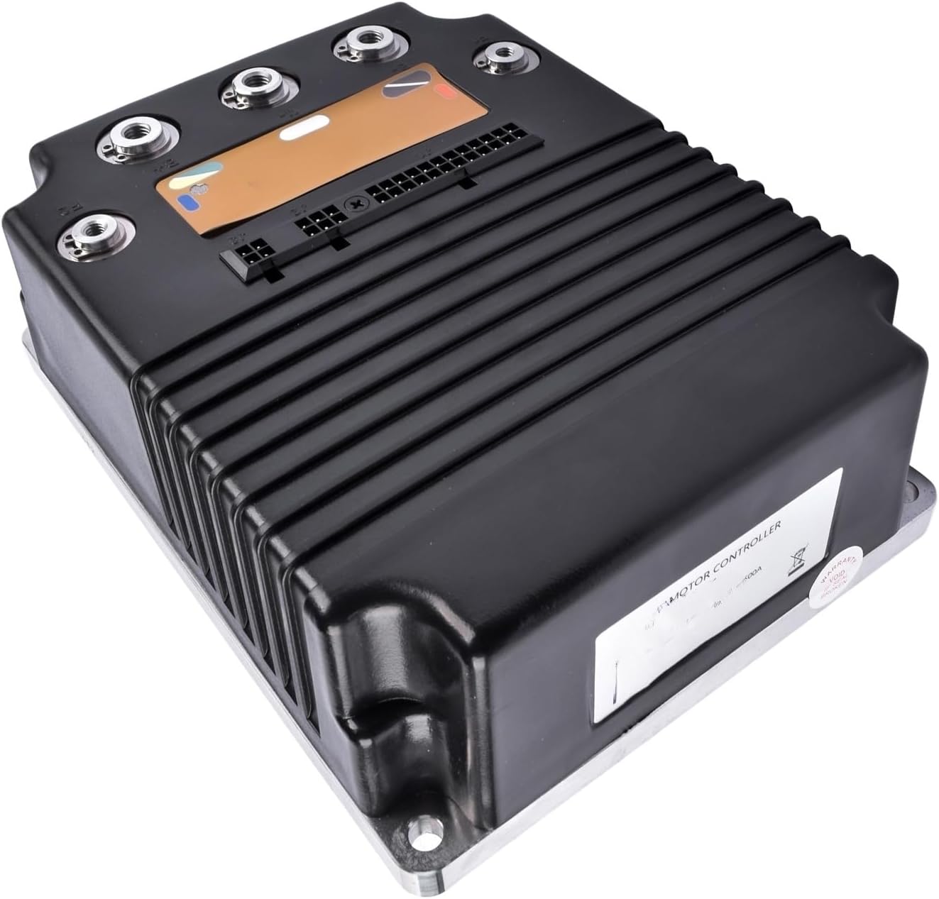
Figure 3.5: Side view of the controller, illustrating its compact form factor and the arrangement of the cooling fins on the top casing.

Figure 3.6: Bottom view of the controller, revealing the flat metal mounting plate. This plate is designed for secure attachment to the golf cart chassis and aids in heat dissipation.
4. Specifications
| Feature | Detail |
|---|---|
| Part Name | DC Motor Controller |
| Part Numbers | 1520-5501, 1027745-01, 102774501, 1520L-5501, 1520L-5550, 105075201, 1050752-01 |
| Application | Compatible with Curtis Club Car Golf Cart |
| Voltage | 48V (Inferred from product title) |
| Current Rating | 500A (Inferred from product title) |
| Brand | IMIFAFTAbT |
| UPC | 751662116027 |
| ASIN | B0FPCPBCM7 |
5. Installation
Installation of a DC motor controller requires electrical knowledge and should ideally be performed by a qualified technician. Incorrect installation can lead to severe damage to the controller, motor, or golf cart, and may pose a safety risk.
5.1 Pre-Installation Checks
- Verify that the new controller's part numbers (1520-5501, 1027745-01, 1050752-01) match the requirements for your Curtis Club Car Golf Cart.
- Ensure the golf cart's battery system is fully disconnected and de-energized.
- Inspect the new controller for any visible damage.
5.2 Mounting the Controller
- Locate the mounting position for the controller, typically where the old controller was removed.
- Secure the controller firmly using appropriate fasteners. Ensure good contact with the mounting surface for optimal heat dissipation.
5.3 Electrical Connections
Refer to the specific wiring diagram for your Curtis Club Car Golf Cart model. General connections include:
- Battery Connections: Connect the main positive and negative battery cables to the designated terminals on the controller.
- Motor Connections: Connect the motor field and armature wires to the corresponding terminals.
- Control Wiring: Connect the throttle input, key switch, direction switch, and other auxiliary control wires to the multi-pin connectors as per the golf cart's wiring diagram.
- Ensure all connections are tight and free from corrosion.
5.4 Post-Installation Checks
- Double-check all wiring for correctness and security.
- Ensure no tools or loose items are left near the electrical components.
- Reconnect the battery system.
- Perform initial power-up and functional tests in a safe, open area.
6. Operation
Once correctly installed, the IMIFAFTAbT DC Motor Controller will manage the power flow to your golf cart's motor based on throttle input and other control signals. The operation of the golf cart itself remains unchanged. Always operate your golf cart according to its manufacturer's guidelines.
- Turn the key switch to the "ON" position.
- Select the desired direction (Forward/Reverse).
- Depress the accelerator pedal to engage the motor.
- Release the accelerator pedal to slow down or stop.
If the golf cart does not respond as expected, refer to the Troubleshooting section.
7. Maintenance
The IMIFAFTAbT DC Motor Controller is designed for durability and requires minimal maintenance. However, periodic checks can help ensure its longevity and optimal performance.
- Visual Inspection: Periodically inspect the controller for any signs of physical damage, corrosion, or loose connections.
- Cleaning: Keep the controller free from dirt, dust, and moisture. Use a dry, soft cloth for cleaning. Do not use harsh chemicals or solvents.
- Connection Checks: Ensure all electrical connections remain tight and secure. Loose connections can cause overheating and intermittent operation.
- Heat Dissipation: Ensure the area around the controller is clear to allow for proper airflow and heat dissipation.
8. Troubleshooting
If you encounter issues with your golf cart's motor control, consider the following common troubleshooting steps. Always disconnect battery power before inspecting electrical components.
| Problem | Possible Cause | Solution |
|---|---|---|
| Golf cart does not move. | No power to controller, faulty key switch, throttle issue, motor problem, or controller fault. | Check battery connections, key switch, and throttle sensor. Verify motor continuity. If issues persist, consult a technician. |
| Intermittent operation. | Loose wiring connections, corroded terminals, or intermittent sensor fault. | Inspect and tighten all electrical connections. Clean any corroded terminals. |
| Controller gets excessively hot. | Overload, poor ventilation, or internal fault. | Ensure proper ventilation around the controller. Avoid overloading the golf cart. If overheating continues, seek professional diagnosis. |
| Unusual noises from motor/controller. | Motor issue, bearing failure, or internal controller fault. | Discontinue use immediately. Have the motor and controller inspected by a qualified technician. |
Important Note: If you are unsure about the suitability of this product or require further assistance, please contact customer support. Provide your original product picture and part number for accurate guidance.
9. Warranty and Support
Specific warranty details for the IMIFAFTAbT DC Motor Controller are typically provided at the point of purchase or with the product packaging. Please retain your proof of purchase for warranty claims.
For technical support, questions regarding compatibility, or assistance with troubleshooting, please contact IMIFAFTAbT customer service. When contacting support, it is helpful to have the following information ready:
- Product Part Number (e.g., 1520-5501, 1027745-01, 1050752-01)
- Description of the issue
- Details of your Curtis Club Car Golf Cart model
- Original product picture and part number (as requested in product description for suitability checks)