1. Introduction
The XTLECLYR XL830L is a compact and versatile digital multimeter designed for measuring DC and AC voltage, DC current, resistance, diode forward voltage drop, and transistor hFE. It features a clear digital display with backlight, data hold function, and low battery indication, making it suitable for various electrical testing and troubleshooting tasks.
2. Safety Information
WARNING: To avoid electric shock or personal injury, please read and understand all safety information before using this multimeter.
- Always ensure the test leads are in good condition and properly connected to the correct input jacks for the measurement being performed.
- Do not apply voltage or current that exceeds the maximum rated values for each range.
- Never measure voltage on a circuit with the function switch set to current, resistance, or diode/transistor test.
- Exercise extreme caution when working with voltages above 30V AC RMS, 42V peak, or 60V DC. These voltages pose a shock hazard.
- Before measuring resistance, diode, or continuity, ensure the circuit is de-energized and all capacitors are discharged.
- Replace the battery when the low battery indicator appears to ensure accurate readings.
- Do not operate the meter if it appears damaged or if the casing is open.
3. Product Overview
Familiarize yourself with the components of your XL830L Digital Multimeter:

Figure 3.1: Labeled diagram of the XL830L Digital Multimeter. This image highlights key features such as the LCD display, data retention button, various measurement ranges (DC voltage, resistance, diode), the backlight button, the OFF key, the transistor DC current measurement area, and the low battery indication symbol.
- LCD Display: Shows measurement readings, units, and function indicators.
- Rotary Switch: Used to select the desired measurement function and range.
- HOLD Button: Freezes the current reading on the display. Press again to release.
- BACK LIGHT Button: Activates the display backlight for better visibility in low-light conditions.
- COM Jack: Common input jack for all measurements. Connect the black test lead here.
- VΩmA Jack: Input jack for voltage, resistance, and current measurements up to 200mA. Connect the red test lead here.
- 10A MAX Unfused Jack: Input jack for high current measurements (up to 10A). Connect the red test lead here for current measurements above 200mA.
- hFE Socket: Used for testing transistors.
4. Setup
4.1. Battery Installation
The XL830L multimeter requires one 9V (6F22) battery (not included) for operation.
- Ensure the multimeter is turned OFF.
- Locate the battery compartment cover on the back of the unit.
- Use a screwdriver to remove the screw securing the battery cover.
- Carefully remove the cover.
- Connect a new 9V battery to the battery clips, observing correct polarity.
- Place the battery into the compartment and replace the cover, securing it with the screw.
5. Operating Instructions
5.1. Measuring DC Voltage (V–)
To measure DC voltage, such as from batteries or DC power supplies:
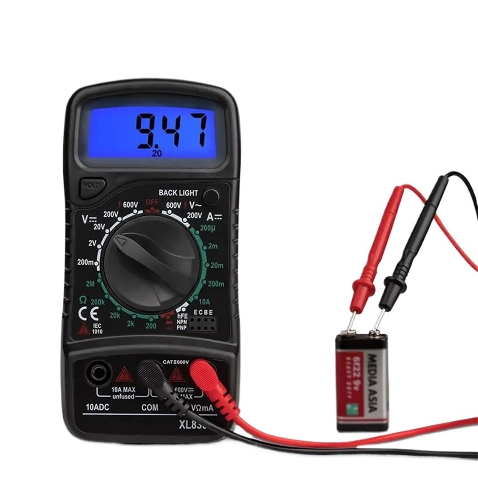
Figure 5.1: The XL830L Digital Multimeter measuring the voltage of a 9V battery. The display shows a reading of 9.47, indicating 9.47 Volts DC.
- Insert the black test lead into the COM jack and the red test lead into the VΩmA jack.
- Turn the rotary switch to the desired V– (DC Voltage) range. Start with the highest range if the voltage is unknown, then decrease the range for better resolution. Available ranges: 200mV, 2V, 20V, 200V, 600V.
- Connect the test probes across the component or circuit to be measured. The red probe to the positive (+) side and the black probe to the negative (-) side.
- Read the voltage value on the LCD display.
5.2. Measuring AC Voltage (V∼)
To measure AC voltage, such as from wall outlets:
- Insert the black test lead into the COM jack and the red test lead into the VΩmA jack.
- Turn the rotary switch to the desired V∼ (AC Voltage) range. Start with the highest range if the voltage is unknown. Available ranges: 200V, 600V.
- Connect the test probes across the AC voltage source.
- Read the voltage value on the LCD display.
5.3. Measuring DC Current (A–)
To measure DC current, the multimeter must be connected in series with the circuit. This requires breaking the circuit to insert the meter.
- For currents up to 200mA: Insert the black test lead into the COM jack and the red test lead into the VΩmA jack.
- For currents between 200mA and 10A: Insert the black test lead into the COM jack and the red test lead into the 10A MAX Unfused jack.
- Turn the rotary switch to the desired A– (DC Current) range. Start with the highest range if the current is unknown. Available ranges: 200µA, 2mA, 20mA, 200mA, 10A.
- De-energize the circuit. Open the circuit where you want to measure current.
- Connect the multimeter in series with the circuit. The current will flow through the meter.
- Re-energize the circuit and read the current value on the LCD display.
- De-energize the circuit before disconnecting the multimeter.
5.4. Measuring Resistance (Ω)
To measure resistance, ensure the component is isolated from the circuit and de-energized.

Figure 5.2: The XL830L Digital Multimeter measuring the resistance of a component. The display shows a reading of 2.36, indicating 2.36 kOhms when the range is set to 2k.
- Insert the black test lead into the COM jack and the red test lead into the VΩmA jack.
- Turn the rotary switch to the desired Ω (Resistance) range. Available ranges: 200Ω, 2kΩ, 20kΩ, 200kΩ, 2MΩ.
- Connect the test probes across the component whose resistance you want to measure.
- Read the resistance value on the LCD display.
5.5. Diode Test
The diode test function allows you to check the forward voltage drop of a diode and its functionality.
- Insert the black test lead into the COM jack and the red test lead into the VΩmA jack.
- Turn the rotary switch to the △ (Diode) position.
- Connect the red probe to the anode and the black probe to the cathode of the diode. The display will show the forward voltage drop (typically 0.5V to 0.8V for silicon diodes).
- Reverse the probes. The display should show 'OL' (Overload) for a good diode, indicating high resistance in the reverse direction.
5.6. Transistor hFE Test
This function allows you to measure the DC current gain (hFE) of NPN and PNP transistors.
- Turn the rotary switch to the hFE position.
- Identify the Emitter (E), Base (B), and Collector (C) leads of the transistor.
- Insert the transistor leads into the corresponding holes in the hFE socket (NPN or PNP side).
- Read the hFE value on the LCD display.
5.7. Continuity Test
The continuity test checks for a complete circuit path and indicates it with an audible beep.
- Insert the black test lead into the COM jack and the red test lead into the VΩmA jack.
- Turn the rotary switch to the △ (Diode) position (this position often includes continuity).
- Connect the test probes across the circuit or component you want to test for continuity.
- If there is a continuous path (low resistance), the meter will beep. The display will show the resistance value. If the circuit is open, the display will show 'OL'.
5.8. Data Hold Function
Press the HOLD button to freeze the current reading on the display. This is useful when taking measurements in hard-to-reach areas. Press the button again to release the hold and resume live readings.
5.9. Backlight Function
Press the BACK LIGHT button to illuminate the display. This improves visibility in dimly lit environments. Press the button again to turn off the backlight.
6. Maintenance
6.1. Cleaning
Wipe the meter's casing with a damp cloth and a mild detergent. Do not use abrasives or solvents. Ensure the meter is completely dry before use.
6.2. Battery Replacement
When the low battery symbol (□) appears on the display, replace the 9V battery as described in Section 4.1. A weak battery can lead to inaccurate readings.
6.3. Fuse Replacement
The 10A input jack is unfused. The VΩmA input jack is typically fused internally. If the meter fails to measure current in the mA ranges, the internal fuse may need replacement. This should only be performed by qualified personnel.
7. Troubleshooting
- No Display: Check battery installation and ensure the battery is charged.
- 'OL' on Display: Indicates overload or out-of-range measurement. Select a higher range or check for an open circuit.
- Incorrect Readings: Check battery level, ensure test leads are properly connected, and verify the correct function and range are selected. Ensure the circuit is de-energized for resistance/diode measurements.
- No Beep in Continuity Test: Check if the circuit is truly continuous (low resistance).
8. Specifications
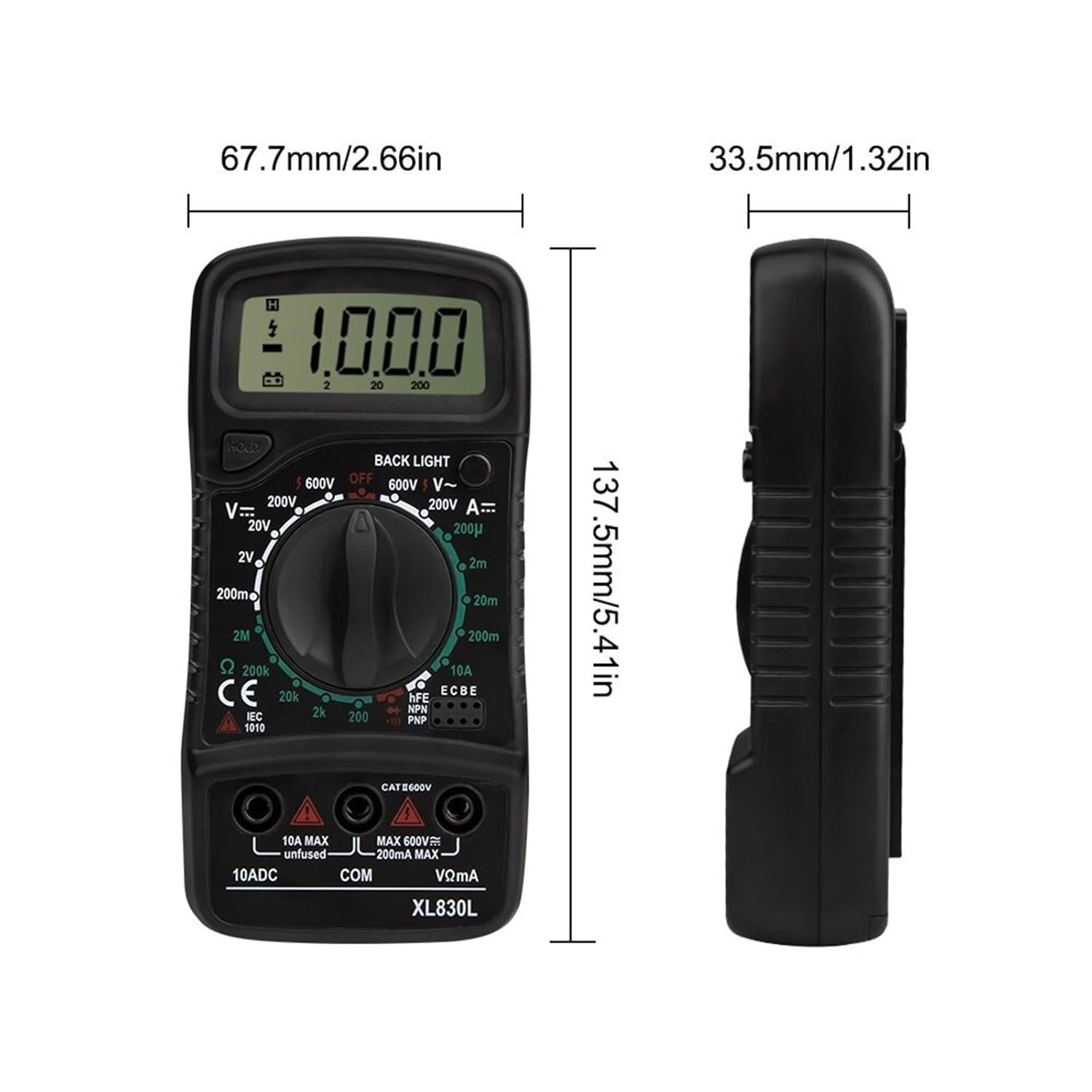
Figure 8.1: Physical dimensions of the XL830L Digital Multimeter.
| Feature | Specification |
|---|---|
| Model Number | XL830L |
| Measuring Current Range (DC) | 200µA, 2mA, 20mA, 200mA, 10A |
| Measuring Voltage Range (DC) | 200mV, 2V, 20V, 200V, 600V |
| Measuring Voltage Range (AC) | 200V, 600V |
| Measuring Resistance Range | 200Ω, 2kΩ, 20kΩ, 200kΩ, 2MΩ |
| Diode Test | Yes |
| Transistor Measurement (hFE) | Yes |
| On-off Beep Test (Continuity) | Yes |
| Dimensions | 137.5mm x 67.7mm x 33.5mm (5.41in x 2.66in x 1.32in) |
| Power | 6F22 9V battery (not included) |
| Backlight Function | Yes |
| Low Voltage Symbol Display | Yes |
| Item Weight | 1.76 ounces |