
Introduction
This manual provides comprehensive instructions for the Enco Drill Milling Machine models 105-1110, 105-1102, and 105-1109. It is a reproduction of the original operator's instructions and parts manual, designed to assist users with the proper installation, operation, adjustment, and maintenance of their machine. This document includes detailed information on various aspects of the machine's functionality and components.
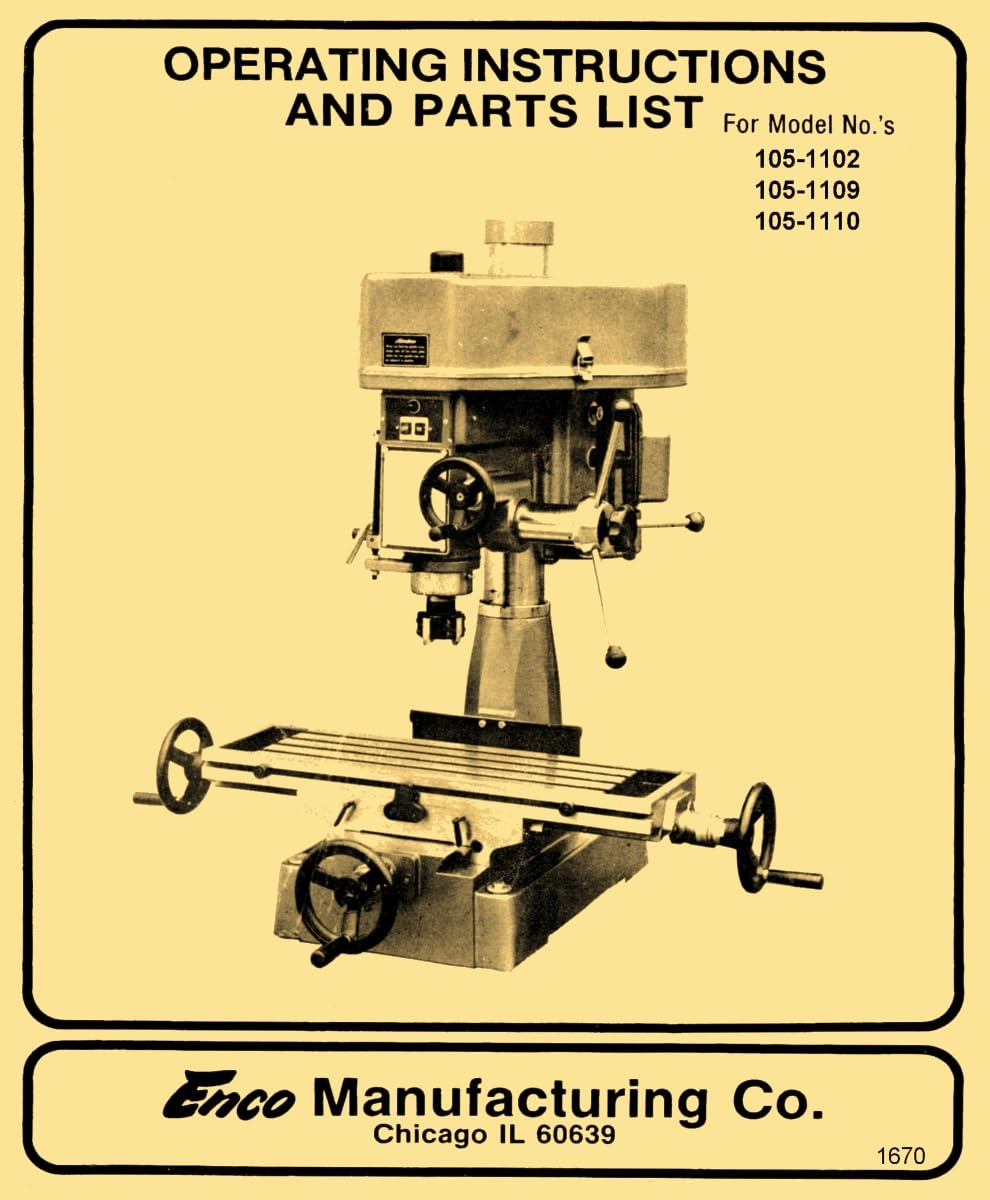
Figure 1: Cover of the Enco Drill Milling Machine Instruction Manual. This image represents the manual itself, which contains detailed instructions and diagrams for the machine.
Installation Instructions
Proper installation is crucial for the safe and efficient operation of your Enco Drill Milling Machine. This section outlines the necessary steps for setting up the machine in your workspace.
- Unpacking: Carefully remove the machine from its packaging. Inspect for any shipping damage.
- Placement: Position the machine on a stable, level surface capable of supporting its weight. Ensure adequate clearance around the machine for operation and maintenance.
- Anchoring: Secure the machine to the workbench or floor using appropriate fasteners to prevent movement during operation.
- Electrical Connection: Connect the machine to a power source that matches the voltage and current requirements specified on the machine's nameplate. Ensure proper grounding.
Operating Instructions
This section details the procedures for operating the Enco Drill Milling Machine safely and effectively.
- Safety Precautions: Always wear appropriate personal protective equipment (PPE), including safety glasses, before operating the machine. Ensure all guards are in place.
- Workpiece Setup: Securely clamp the workpiece to the machine table. Verify that the clamping is rigid and will not shift during machining.
- Tool Installation: Select the appropriate drill bit or milling cutter. Insert the tool into the spindle collet or chuck and tighten securely.
- Machine Start-up: Turn on the main power switch. Select the desired spindle speed according to the material and tool being used.
- Operation: Carefully bring the tool into contact with the workpiece. Apply feed slowly and consistently. Monitor the cutting process for any unusual sounds or vibrations.
- Machine Shut-down: Once machining is complete, retract the tool, turn off the spindle, and then turn off the main power switch.
Adjustments
This section covers various adjustments that may be required for optimal machine performance.
- Spindle Head Tilt: Instructions for tilting the spindle head for angled drilling or milling operations.
- Table Movement: Guidance on adjusting the X, Y, and Z axis movements of the machine table.
- Gib Adjustments: Procedures for adjusting the gibs on the machine slides to eliminate play and ensure smooth, precise movement.
- Depth Stop: How to set and use the depth stop for consistent drilling or milling depths.
Motor Speed Pulley Chart
The manual includes a motor speed pulley chart to guide users in selecting the correct spindle speed for various operations. This chart is essential for achieving optimal cutting performance and extending tool life.
3-Pulley Models
Refer to the chart below for recommended pulley configurations for 3-pulley systems.
| Motor Pulley Position | Spindle Pulley Position | Approx. RPM |
|---|---|---|
| Small | Large | Low Speed |
| Medium | Medium | Medium Speed |
| Large | Small | High Speed |
4-Pulley Models
Refer to the chart below for recommended pulley configurations for 4-pulley systems.
| Motor Pulley Position | Intermediate Pulley | Spindle Pulley Position | Approx. RPM |
|---|---|---|---|
| Small | Upper | Large | Very Low Speed |
| Medium | Upper | Medium | Low Speed |
| Large | Lower | Small | High Speed |
| Largest | Lower | Smallest | Very High Speed |
Note: Actual RPMs may vary slightly based on motor specifications and belt tension. Always consult the specific chart within your physical manual for precise values.
Tool Removal
This section provides instructions for safely removing cutting tools from the spindle.
- Power Off: Ensure the machine is completely powered off and the spindle has come to a complete stop.
- Loosen Collet/Chuck: Use the appropriate wrench to loosen the collet nut or chuck jaws.
- Remove Tool: Carefully withdraw the cutting tool from the spindle. Avoid dropping the tool.
- Clean: Clean any chips or debris from the collet/chuck and the tool shank before storing.
Parts List and Diagrams
The original manual contains a complete set of exploded view and cross-sectional view diagrams of all the parts, along with a detailed parts list and descriptions. These diagrams are invaluable for identifying components, understanding assembly, and ordering replacement parts.
Note: Due to the nature of this digital reproduction, specific diagrams are not embedded here. Please refer to your physical manual for these detailed illustrations.
Maintenance
Regular maintenance ensures the longevity and performance of your Enco Drill Milling Machine. This includes routine cleaning, lubrication, and inspection.
- Cleaning: Keep the machine free of chips, dust, and debris. Clean the table, ways, and spindle regularly.
- Lubrication: Follow the lubrication schedule outlined in the original manual. Apply appropriate lubricants to all moving parts, including ways, lead screws, and gears.
- Belt Tension: Periodically check and adjust the tension of the drive belts to ensure efficient power transmission and prevent slippage.
- Inspection: Regularly inspect all fasteners for tightness, and check for any signs of wear or damage on components such as bearings, gears, and electrical wiring.
Troubleshooting
This section provides guidance on identifying and resolving common operational issues.
- Machine Not Starting: Check power supply, circuit breaker, and emergency stop button.
- Excessive Vibration: Inspect tool balance, workpiece clamping, and machine leveling. Check for loose components or worn bearings.
- Poor Surface Finish: Verify correct spindle speed, feed rate, and tool sharpness. Ensure machine rigidity and proper gib adjustments.
- Unusual Noises: Investigate for lack of lubrication, worn gears, or loose components.
Specifications
Key specifications for the Enco Drill Milling Machine models 105-1110, 105-1102, and 105-1109 are provided below. These details are based on the manual's information.
- Manual Print Length: 18 pages
- Manual Publication Date: September 3, 2000
- Manual Publisher: Ozark Tool Manuals
- Manual Dimensions: 11 x 8.5 x 0.5 inches
- Recommended Reading Age: 18 years and up
Note: Machine-specific operational specifications (e.g., motor horsepower, spindle taper, table travel) are contained within the full manual.
Warranty Information
This document is a reproduction of an instruction manual and does not include warranty information for the original Enco Drill Milling Machine. For details regarding any warranty on the physical machine, please refer to the original purchase documentation or contact the machine manufacturer or reseller directly.
Support
For further assistance with your Enco Drill Milling Machine, it is recommended to consult the complete physical manual for detailed diagrams and specific model information. For technical support related to the machine itself, please contact a qualified machinery technician or the original equipment manufacturer.
For inquiries regarding this reproduction manual, please contact Ozark Tool Manuals, the publisher.