NCLTHS CK88-C-1200LBS
NCLTHS Access Control System Kit CK88-C-1200LBS User Manual
Model: CK88-C-1200LBS
1. Introduction
This manual provides comprehensive instructions for the installation, operation, and maintenance of your NCLTHS Access Control System Kit, model CK88-C-1200LBS. This system is designed to provide secure and convenient access management for various environments, including homes, offices, and commercial spaces. It features multiple access methods, including RFID cards, passwords, and remote control.
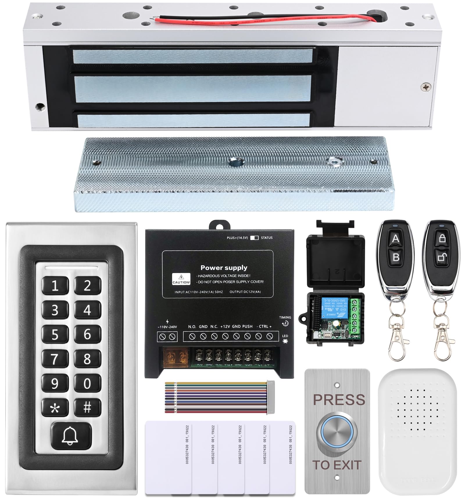
Image 1.1: Overview of the NCLTHS Access Control System Kit components.
2. Package Contents
Verify that all items listed below are included in your package. If any items are missing or damaged, please contact customer support.
- 1 x Access Control Keypad (Model CK88-s)
- 1 x 1200lbs Fail-Safe Electromagnetic Lock
- 1 x 12V DC Power Supply Control
- 1 x Push to Exit Button (Stainless Steel)
- 1 x Doorbell
- 2 x Remote Controls (with receiver module)
- 5 x RFID Cards
- 1 x English User Manual (this document)
- Mounting Hardware (screws, anchors, L-brackets, Z-brackets, etc.)

Image 2.1: All components included in the NCLTHS Access Control System Kit.
3. Safety Information
Please read and understand all safety instructions before installation and operation. Failure to follow these instructions may result in electric shock, fire, or serious injury.
- Electrical Safety: Installation involves electrical wiring. If you are not comfortable with electrical work, consult a qualified electrician. Ensure power is disconnected before performing any wiring.
- Power Supply: Use only the provided 12V DC power supply. Do not attempt to open or modify the power supply unit.
- Mounting: Ensure all components are securely mounted to a stable surface to prevent accidental detachment.
- Environment: Do not expose the system components to extreme temperatures, moisture, or corrosive environments.
- Children: Keep all components and packaging materials out of reach of children.
4. Setup and Installation
This section guides you through the physical installation and wiring of the access control system components.
4.1 Component Overview
Familiarize yourself with each component before beginning installation.

Image 4.1.1: Access Control Keypad (Model CK88-s).

Image 4.1.2: 1200lbs Fail-Safe Electromagnetic Lock.

Image 4.1.3: 12V DC Power Supply Control Unit.

Image 4.1.4: Stainless Steel Push to Exit Button.
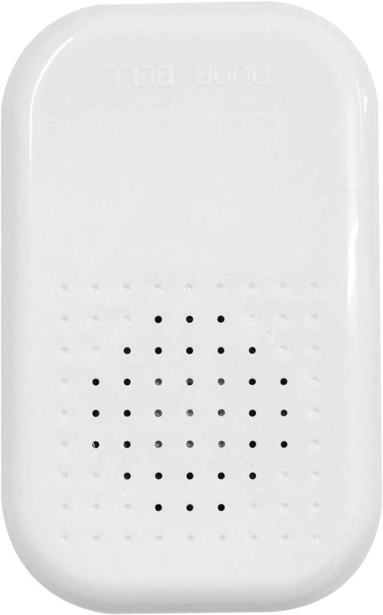
Image 4.1.5: Doorbell Unit.
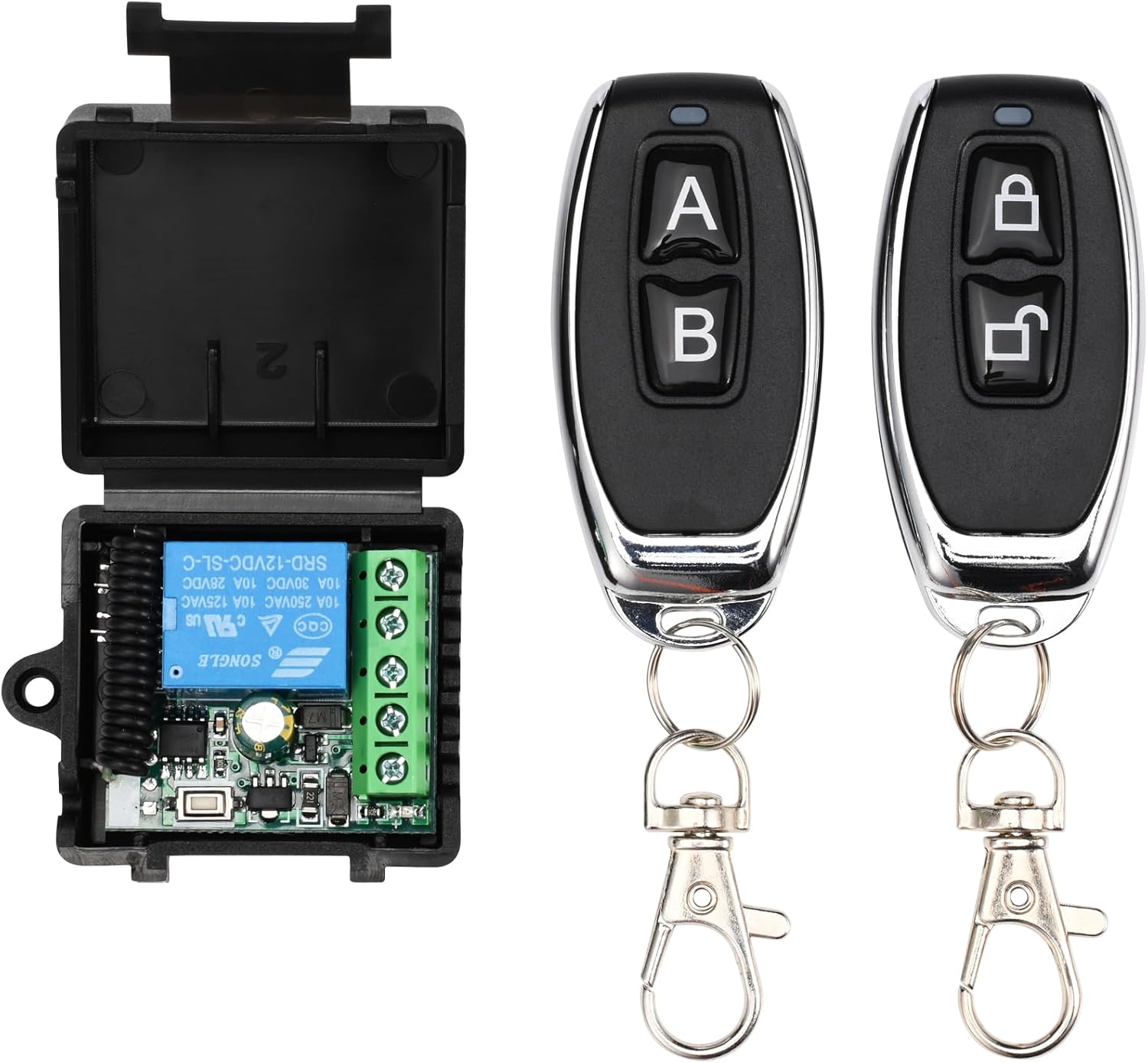
Image 4.1.6: Remote Controls and Receiver Module.
4.2 Wiring Diagram
Refer to the following wiring diagram for connecting all components. Ensure all connections are secure and correctly matched.

Image 4.2.1: Comprehensive wiring diagram for the access control system.
- Connect the Electromagnetic Lock to the Power Supply's "NO" (Normally Open) and "GND" terminals.
- Connect the Keypad to the Power Supply's "+12V", "GND", "NO", "NC", "COM", and "BELL" terminals as indicated.
- Connect the Exit Button to the Power Supply's "PUSH" and "GND" terminals.
- Connect the Doorbell to the Power Supply's "BELL" and "+12V" terminals.
- Connect the Remote Receiver Module to the Power Supply's "+12V", "GND", "COM", and "NO" terminals.
- Ensure the main power input to the Power Supply is correctly connected to AC 110-240V.
4.3 Mounting Instructions
Follow these general steps for mounting the components. Specific mounting hardware and methods may vary based on your door type and wall material.
- Electromagnetic Lock:
- Mount the main lock body to the door frame using the provided screws and brackets (L-bracket for inswing doors, Z-bracket for outswing doors).
- Mount the armature plate to the door itself, ensuring it aligns perfectly with the electromagnetic lock body when the door is closed.
- Keypad:
- Choose a suitable location near the door, typically at eye level.
- Drill holes for mounting screws and cable routing.
- Secure the keypad to the wall.
- Power Supply:
- Mount the power supply unit in a secure, dry, and accessible location, away from direct sunlight or moisture.
- Exit Button & Doorbell:
- Mount the exit button on the inside of the door frame.
- Mount the doorbell button on the outside, near the keypad.
- Remote Receiver:
- Mount the receiver module in a discreet location, ensuring its antenna is not obstructed for optimal signal reception.
5. Operating Instructions
This section details how to use and program your access control system.
5.1 Initial Setup and Master Code
- The default master code is usually 123456. It is highly recommended to change this immediately after installation.
- To enter programming mode: Press * then enter the Master Code, then press #. The indicator light will change.
5.2 Changing the Master Code
- Enter programming mode: * [Default Master Code] #
- Press 0 (for changing master code).
- Enter your new 6-digit Master Code.
- Press # to confirm.
- Exit programming mode: Press *
5.3 Adding User Cards (RFID)
- Enter programming mode: * [Master Code] #
- Press 1 (for adding user card).
- Present the RFID card to the keypad. The keypad will beep to confirm.
- Repeat for additional cards.
- Exit programming mode: Press *
5.4 Adding User Passwords
- Enter programming mode: * [Master Code] #
- Press 2 (for adding user password).
- Enter a 4-6 digit user password.
- Press # to confirm.
- Repeat for additional passwords.
- Exit programming mode: Press *
5.5 Deleting Users
- Enter programming mode: * [Master Code] #
- Press 3 (for deleting user).
- To delete a card: Present the RFID card to the keypad.
- To delete a password: Enter the 4-6 digit user password, then press #.
- Exit programming mode: Press *
5.6 Accessing the Door
- Using RFID Card: Present your registered RFID card to the keypad. The door will unlock briefly.
- Using Password: Enter your registered 4-6 digit password, then press #. The door will unlock briefly.
- Using Remote Control: Press the unlock button on the remote control. The door will unlock briefly.
- Using Exit Button: From inside, press the "PRESS TO EXIT" button. The door will unlock briefly.
5.7 Doorbell Function
When the bell button on the keypad is pressed, the connected doorbell unit will chime.
6. Maintenance
Regular maintenance ensures the longevity and optimal performance of your access control system.
- Cleaning: Wipe the keypad and other components with a soft, dry cloth. Do not use abrasive cleaners or solvents.
- Inspection: Periodically check all wiring connections for looseness or damage. Ensure the electromagnetic lock and armature plate are free of debris and properly aligned.
- Power Supply: Ensure the power supply unit is well-ventilated and free from obstructions.
- Battery Backup (if applicable): If your power supply unit has a battery backup feature, ensure the battery is in good condition and replaced as needed according to manufacturer guidelines.
7. Troubleshooting
Refer to this section for common issues and their solutions.
| Problem | Possible Cause | Solution |
|---|---|---|
| Door does not unlock. | No power to the system. Incorrect wiring. Invalid card/password. Electromagnetic lock malfunction. | Check power supply connection. Verify all wiring according to the diagram. Ensure correct card/password is used. Inspect the electromagnetic lock for damage. |
| Keypad is unresponsive. | No power to the keypad. Keypad malfunction. | Check keypad wiring to the power supply. Ensure power supply is active. |
| Remote control does not work. | Remote battery low. Remote not paired. Receiver not powered or faulty. | Replace remote battery. Refer to remote pairing instructions (if applicable, usually done during initial setup). Check receiver wiring and power. |
| Doorbell does not chime. | Doorbell unit not powered. Incorrect wiring. Faulty doorbell unit. | Check doorbell wiring to the power supply. Ensure power supply is active. |
If you encounter issues not listed here or if the suggested solutions do not resolve the problem, please contact NCLTHS customer support.
8. Specifications
| Feature | Detail |
|---|---|
| Brand | NCLTHS |
| Model | CK88-C-1200LBS Kit |
| Electromagnetic Lock Holding Force | 1200 lbs |
| Power Source | Hardwired Electrical Connection (AC 110-240V input, DC 12V output) |
| Access Methods | RFID Card, Password, Remote Control |
| Keypad Model | CK88-s |
| Item Dimensions (L x W x H) | 9.84 x 1.93 x 0.84 inches (Keypad) |
| Item Weight | 4.2 Pounds (Total Kit) |
| Smart Home Compatibility | Not Smart Home Compatible |
9. Warranty and Support
For warranty information, technical support, or customer service inquiries, please refer to the contact information provided with your purchase or visit the official NCLTHS website.
Ask a question about this manual
Ask about setup, troubleshooting, compatibility, parts, safety, or missing instructions. Manuals+ will review the question and use this page’s manual context to help answer it.