1. Introduction
This manual provides detailed instructions for the installation, operation, and maintenance of your GRYVOZE 1 Inch Digital Turbine Fuel Flow Meter. This device is designed for accurate measurement of various liquids, including water, fuel, diesel, gasoline, kerosene, and methanol. Please read this manual thoroughly before use to ensure proper function and safety.
2. Safety Instructions
- The flow meter is not waterproof. Avoid submerging it in water or exposing it to harsh, wet environments.
- This electronic fuel meter is not suitable for measuring drinking water, alkaline water, or other corrosive liquids.
- Due to its aluminum alloy casing, it is not recommended for use with highly corrosive chemicals.
- Ensure the flow direction arrow on the meter aligns with the liquid flow in your system.
- The PCB circuit board is not waterproof. Do not allow it to get wet.
- The factory test uses colorless, slightly odorous mineral oil. An appropriate cleaner can be used for cleaning if necessary.
3. What's in the Box
- 1 Inch Flow Meter
- 2 x Male Adapters
- 360° Swivel Connector
4. Product Overview

Figure 4.1: Overview of the GRYVOZE Digital Turbine Flow Meter, highlighting key components such as the Liquid Flow Direction Sign, Set/Query Key, Clear Key, Single Cumulative Flow display, Unit indicator, and Total Cumulative Flow display.
The GRYVOZE Digital Turbine Flow Meter features a robust aluminum alloy housing and a clear LCD display. It includes two buttons for calibration and display functions. The meter is designed with a 360° rotating joint for flexible installation and includes a durable PP turbine for accurate flow measurement.

Figure 4.2: Illustration emphasizing the importance of correct flow direction during installation and showcasing the durable PPS turbine material with tungsten steel bearings for long-lasting performance.
5. Setup and Installation
Proper installation is crucial for accurate readings and longevity of the flow meter.
5.1 Flow Direction
Install the flow meter so that the arrow on the meter's body aligns with the direction of liquid flow. Incorrect orientation will result in inaccurate readings.
5.2 Display Panel Orientation
The display panel can be rotated 180° to adjust to your viewing needs. Simply remove the screws securing the panel, rotate it, and re-secure the screws.
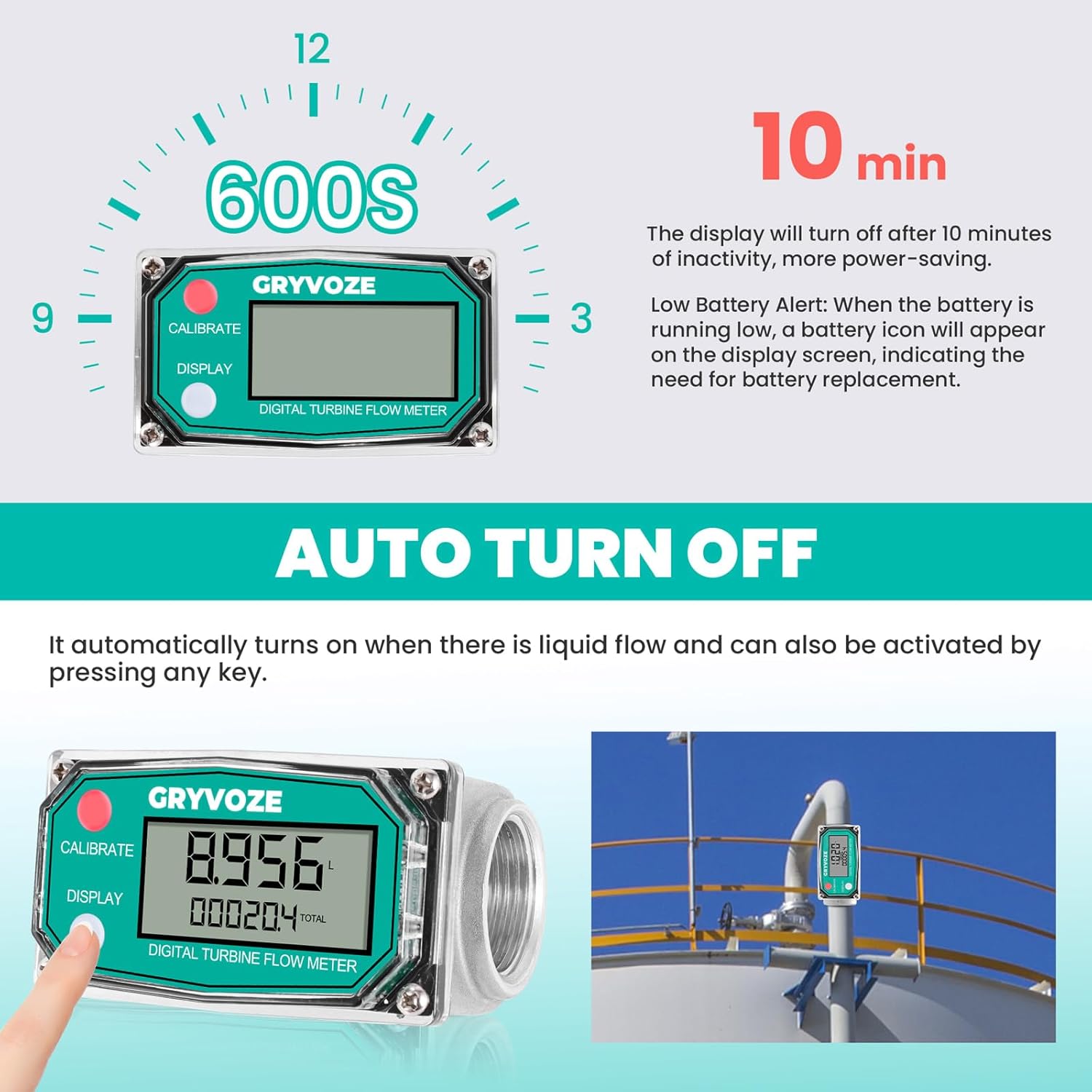
Figure 5.1: The flow meter's display panel can be rotated 180 degrees for optimal viewing, allowing for flexible installation in various orientations.
5.3 Connection
Utilize the provided male adapters and 360° swivel connector for easy integration into your existing pipeline or fuel gun. The swivel connector helps prevent hose tangling and ensures smooth flow.
5.4 Environmental Considerations
Install the meter in a dry environment, protected from moisture. The device is not waterproof.
6. Operating Instructions
6.1 Digital LCD Display
The clear LCD displays the following information:
- Flow Rate: Instantaneous flow of liquid.
- Total Cumulative Flow: The grand total of all measured liquid.
- Single Cumulative Flow: The total for a single measurement session, which can be reset.
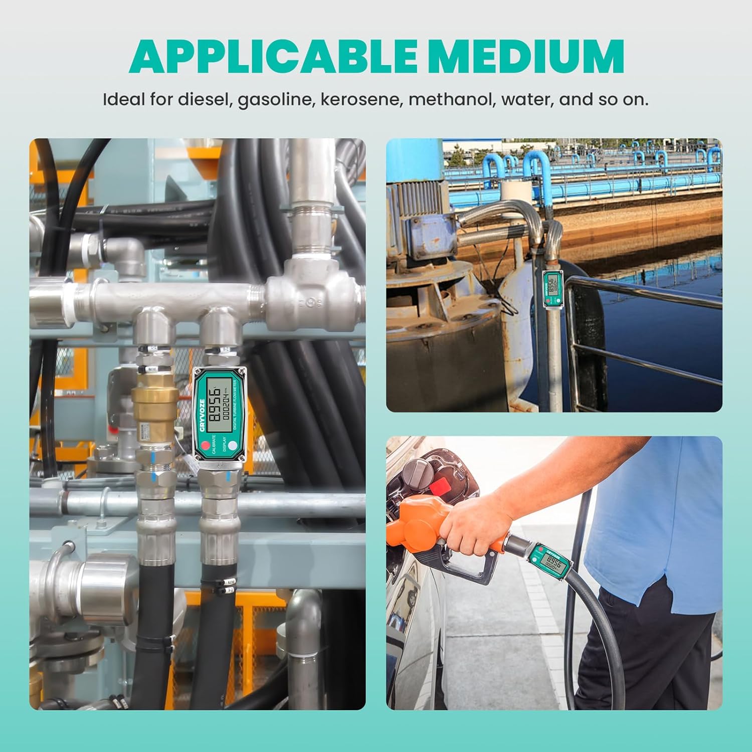
Figure 6.1: The high-definition LCD screen clearly displays instantaneous flow, single accumulated flow, and total accumulated flow, supporting five measurement units for easy viewing.
6.2 Auto Turn-Off Function
The screen automatically turns off after 10 minutes of inactivity to conserve battery life. It reactivates upon detection of liquid flow or by pressing any button.
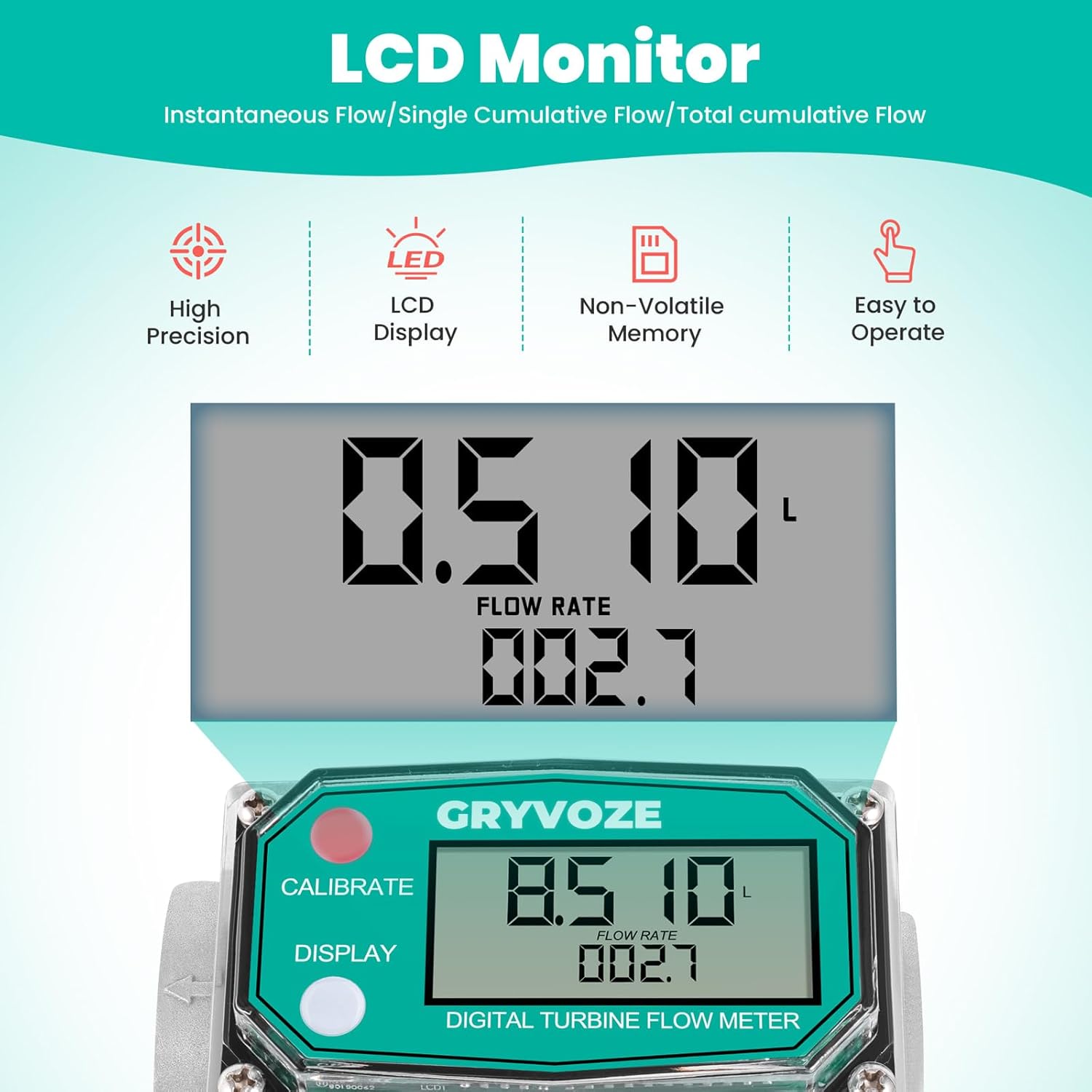
Figure 6.2: The flow meter features an auto turn-off function after 10 minutes of inactivity to save power. The display can be reactivated by liquid flow or button press.
6.3 Unit Switching
The meter supports five measurement units: GAL (US Gallons), QTS (Quarts), PTS (Pints), L (Liters), and m³ (Cubic Meters).

Figure 6.3: The flow meter offers five optional units (GAL, QTS, PTS, L, m³) for flexible measurement needs.
To switch units:
- Simultaneously press and hold both the 'CALIBRATE' (red) and 'DISPLAY' (white) buttons for more than 5 seconds to enter 'unit switching mode'. The current unit will flash.
- Click the 'DISPLAY' (white) button to cycle through the available units (m³, Qts, Pts, L, Gal (US)).
- Long press the 'CALIBRATE' (red) button for 3 seconds to save your selection and exit the unit setting mode.

Figure 6.4: Step-by-step guide on how to switch between different metering units using the 'CALIBRATE' and 'DISPLAY' buttons.
6.4 Calibration
The meter is factory-calibrated with an accuracy of ±1%. For specific applications or to fine-tune accuracy, manual calibration is supported. Refer to the detailed instructions in the included product manual for on-site calibration methods and formulas.
6.5 Resetting Single Cumulative Flow
To clear the single cumulative flow, press and hold the 'DISPLAY' (white) button for 5 seconds. The total cumulative flow remains unaffected.
6.6 Product Functions and Operating Steps Video
Video 6.1: An official GRYVOZE video demonstrating the product's functions and operating steps, including unboxing, component overview, and basic usage instructions.
7. Maintenance
7.1 Battery Replacement
The meter operates on 2 x AAA LR03 batteries. The memory is non-volatile, meaning cumulative data is retained even when batteries are removed or replaced. A battery icon will appear on the display when the battery is running low, indicating the need for replacement. The standby time exceeds 1 year.
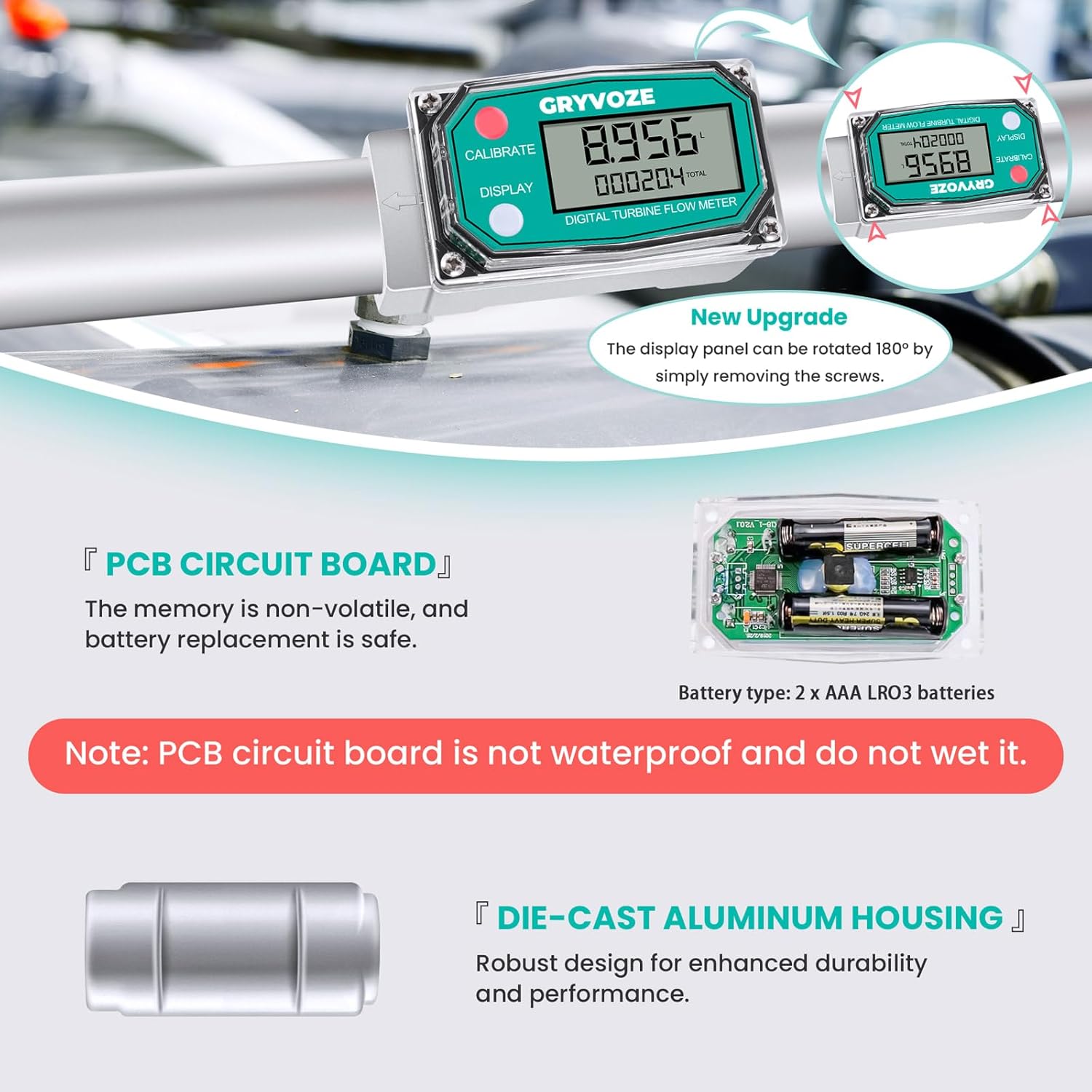
Figure 7.1: View of the PCB circuit board and battery compartment, indicating the use of 2 x AAA LR03 batteries. Note that the PCB circuit board is not waterproof.
7.2 Cleaning
If the meter requires cleaning, use an appropriate cleaner suitable for the materials (aluminum alloy, PP turbine). Avoid using harsh chemicals or submerging the device in water.
8. Troubleshooting
8.1 Inaccurate Readings
- Verify that the flow meter is installed with the correct flow direction.
- Ensure the liquid being measured is within the specified flow range (2.6-26 GPM).
- Check for any blockages or debris in the flow path or turbine.
- Consider performing a manual calibration if accuracy issues persist.
8.2 Display Not Working
- Check battery levels and replace if necessary.
- Ensure the meter is not in auto-sleep mode; initiate flow or press a button to reactivate.
8.3 Electromagnetic Interference
This flow meter is equipped with an anti-electromagnetic interference function, allowing it to be installed closer to pumps or motors without significant impact on readings. If you experience unusual readings near such equipment, ensure proper grounding and installation practices.

Figure 8.1: The flow meter's anti-electromagnetic interference capability allows for installation near pumps or motors, reducing the risk of magnetic field interference that can affect readings.
9. Specifications
| Feature | Specification (1 Inch Model) |
|---|---|
| Material | Aluminum alloy casing, PP turbine |
| Threads Type | NPT |
| Flow Range | 2.6-26 GPM (9-100 LPM) |
| Accuracy | ±1% |
| Maximum Working Pressure | 87 PSI (6 Bar) |
| Applicable Medium | Diesel, gasoline, kerosene, methanol, water, and similar liquids. Not suitable for drinking water, alkaline water, or corrosive liquids. |
| Display | Digital LCD (Flow Rate, Single Cumulative Flow, Total Cumulative Flow) |
| Units | GAL (US Gallons), QTS, PTS, L, m³ |
| Battery Type | 2 x AAA LR03 batteries |
| Auto Turn-Off | After 10 minutes of inactivity |
| Non-Volatile Memory | Yes |
| Package Dimensions | 6.89 x 3.66 x 3.35 inches |
| Item Weight | 1.46 Pounds |

Figure 9.1: Detailed parameter comparison between the 1 inch and 3/4 inch GRYVOZE flow meter models, including material, thread type, flow range, and applicable medium.
10. Support
For further assistance, technical support, or inquiries regarding your GRYVOZE Digital Turbine Fuel Flow Meter, please refer to the contact information provided with your product packaging or visit the official GRYVOZE website.