1. Introduction
This manual provides essential information for the installation, operation, and maintenance of the VOTOL EM100GTS Brushless DC Motor Controller. This intelligent programmable controller is designed for electric motorcycles and motor scooters, offering efficient power management for 2000 to 4000-watt motors. Please read this manual thoroughly before installation and use to ensure proper function and safety.
2. Safety Information
- Always disconnect power before performing any installation, maintenance, or troubleshooting.
- Ensure all wiring connections are secure and correctly polarized to prevent damage to the controller or motor.
- Avoid exposing the controller to water, excessive moisture, or extreme temperatures.
- Do not attempt to open or modify the controller casing, as this may void the warranty and pose a safety risk.
- Consult a qualified technician if you are unsure about any installation or wiring procedures.
3. Product Overview
The VOTOL EM100GTS controller is a high-performance unit designed to manage brushless DC motors. It features weak magnetic technology to enhance power and speed. The controller supports a universal voltage range of 60V to 84V, with a maximum release current of 200A and a phase line current of 400A.
Key Features:
- Voltage Compatibility: 60V to 84V universal.
- Current Capacity: Max 200A release current, 400A phase line current.
- Motor Adaptability: Suitable for 2000W to 4000W motors.
- Advanced Technology: Incorporates weak magnetic technology for improved performance.
- Programmable Functions: Supports various customizable settings via software.
Controller Components and Views:

Figure 3.1: Top view of the EM100GTS controller. This image displays the main body of the controller with its various connection ports, including the Hall Plug, program port, and power terminals. Warning labels and torque specifications are visible.

Figure 3.2: Angled view of the EM100GTS controller. This perspective shows the arrangement of the multi-pin connectors and power terminals, providing a clearer view of the input/output interfaces.

Figure 3.3: Bottom view of the EM100GTS controller. This image highlights the integrated heat sink design, crucial for dissipating heat during operation and maintaining optimal performance.

Figure 3.4: Side view of the EM100GTS controller. This view provides a detailed look at the side-mounted wiring ports and their labels, essential for correct electrical connections.
4. Included Components
The VOTOL EM100GTS controller package includes the following items:
- VOTOL EM100GTS Controller Unit
- Matching Wiring Harness
- USB Debugging Data Cable
5. Setup and Installation
Proper installation is critical for the safe and efficient operation of your EM100GTS controller. Always refer to the wiring diagram provided with your specific motor and vehicle for precise connections. The included matching wiring harness is designed to facilitate these connections.
General Installation Steps:
- Mounting: Securely mount the controller in a location that is protected from direct impact, excessive vibration, and moisture. Ensure adequate airflow for heat dissipation, especially around the heat sink fins (refer to Figure 3.3).
- Power Connections: Connect the main power cables from the battery to the controller, observing correct polarity.
- Motor Connections: Connect the motor phase wires and Hall sensor wires to the corresponding ports on the controller. The controller supports Hall Plug connections.
- Accessory Connections: Connect other functional wires such as throttle (0-5V), brake signals (Low Brake 0V, High Brake 12V), ignition, three-speed switch, sport mode switch, parking, anti-theft, and regen charge as required by your vehicle's setup.
- Programming Port: The program port is used for connecting the USB debugging data cable to a computer for software configuration.
Note: Incorrect wiring can cause severe damage to the controller, motor, or battery. If you are not confident in your ability to perform the installation, seek professional assistance.
6. Operating Instructions and Programming
The VOTOL EM100GTS controller offers a range of default functions and programmable settings to optimize your electric vehicle's performance. The included USB debugging data cable allows connection to a computer for detailed configuration.
Default Functions:
- Hall Plug
- Reverse Function
- Low Brake (0V)
- Throttle (0-5V)
- High Brake (12V)
- Ignition
- One-line/Hall Meter Wire
- Program Port
- Three Speed Modes
- Sport Model
- Parking Function
- Anti-Theft System
- Regen Charge (Regenerative Braking)
- Flux Weaken Current
Software Programming Interface:
The controller's performance parameters can be fine-tuned using the dedicated software interface. Connect the controller to your computer using the USB debugging data cable. The software allows adjustment of various parameters including voltage settings, current limits, throttle response, motor type, and more.

Figure 6.1: Software Interface - Basic Settings. This screen allows configuration of fundamental parameters such as battery voltage, undervoltage protection, busbar current, phase current, and throttle voltage settings.

Figure 6.2: Software Interface - Sport Mode and Flux Weakening. This section provides controls for current limiting, flux weakening values, automatic logout enablers, and settings for downhill electric brake assist (HDC/HHC).
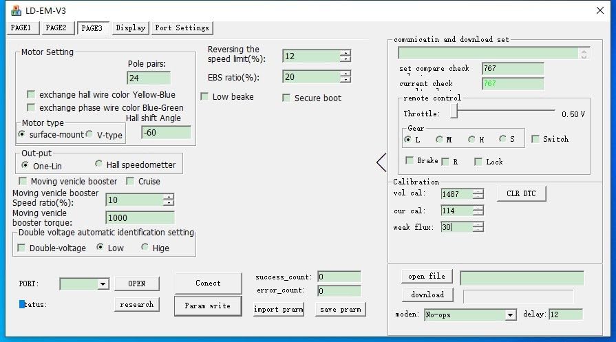
Figure 6.3: Software Interface - Motor Settings. Here, users can configure motor-specific parameters such as pole pairs, Hall wire color exchange, motor type (surface-mount/V-type), and options for moving vehicle booster and cruise control.
Always save your configuration changes after making adjustments. Refer to the software's help documentation for detailed explanations of each parameter.
7. Maintenance
The VOTOL EM100GTS controller is designed for durability and requires minimal maintenance. Follow these guidelines to ensure its longevity:
- Cleaning: Keep the controller clean and free from dust and debris. Use a dry, soft cloth for cleaning. Do not use liquid cleaners.
- Inspection: Periodically inspect all wiring connections for tightness and signs of wear or corrosion.
- Environment: Ensure the controller remains in a well-ventilated area, protected from extreme temperatures and moisture.
8. Troubleshooting
If you encounter issues with your EM100GTS controller, consider the following basic troubleshooting steps:
- No Power: Check all power connections from the battery to the controller and ensure the ignition is on. Verify battery voltage.
- Motor Not Responding: Verify throttle connections and functionality. Check motor phase and Hall sensor wiring. Ensure no brake signals are active.
- Erratic Behavior: Recheck all wiring for loose connections or shorts. If programmable, review software settings for any incorrect parameters.
- Overheating: Ensure the controller is mounted in a location with adequate airflow and that the heat sink is not obstructed. Reduce continuous high-load operation if possible.
For persistent issues, consult the manufacturer's support resources or a qualified technician.
9. Specifications
| Parameter | Value |
|---|---|
| Model | EM100GTS |
| Voltage Range | 60V to 84V (Universal) |
| Max Release Current | 200A |
| Phase Line Current | 400A |
| Adaptive Motor Power | 2000W to 4000W |
| Package Dimensions | 7.87 x 4.72 x 3.94 inches |
| Manufacturer | Zhejiang Qima Co., Ltd. |
10. Warranty and Support
For warranty information, technical support, or service inquiries, please contact the manufacturer, Zhejiang Qima Co., Ltd., or your authorized dealer. Keep your purchase receipt as proof of purchase for warranty claims.