GYQSSD o9sc-878980
GYQSSD 5500W All-in-One Hybrid Solar Inverter User Manual
Model: o9sc-878980
1. Introduction
This user manual provides comprehensive instructions for the installation, operation, maintenance, and troubleshooting of your GYQSSD 5500W All-in-One Hybrid Solar Inverter. This advanced system integrates a 120A MPPT charge controller, a pure sine wave inverter, and an AC charger, offering a complete energy storage solution for off-grid applications and power backup.
Designed for reliability and efficiency, this inverter ensures seamless power supply for critical loads with a transfer speed of less than 10ms. Please read this manual thoroughly before installation and operation to ensure safe and optimal performance of your inverter.
2. Safety Instructions
Always adhere to the following safety precautions to prevent injury and damage to the inverter:
- Installation must be performed by qualified personnel.
- Ensure all power sources are disconnected before installation or maintenance.
- Do not disassemble the inverter. There are no user-serviceable parts inside.
- Keep the inverter away from water, moisture, and flammable materials.
- Ensure proper ventilation around the unit to prevent overheating.
- Use appropriate personal protective equipment (PPE) during installation.
3. Product Overview
The GYQSSD 5500W All-in-One Hybrid Solar Inverter is a versatile power solution designed for various applications, including RVs, marine use, home backup, and off-grid systems. It provides a pure sine wave output, ensuring compatibility with sensitive electronics.
3.1 Key Features
- Integrated 5500W Hybrid Solar Inverter with 100A MPPT Charge Controller and AC Charger.
- Intuitive LCD panel for real-time system data display.
- WiFi connectivity for remote monitoring via mobile app or web portal.
- Compatible with various 48V battery types (AGM, Gel, Lithium-ion) and supports battery-less mode.
- Multiple charging modes: PV priority, Utility priority, Hybrid charging, Solar only charging.
- Two output modes: Utility bypass and Inverter output.
- Pure Sine Wave output for sensitive electronics.
- Supports parallel operation for up to 8 units (Max. 44kW).
3.2 Product Components and Diagram

Figure 3.1: GYQSSD 5500W All-in-One Hybrid Solar Inverter in a typical solar power system setup.
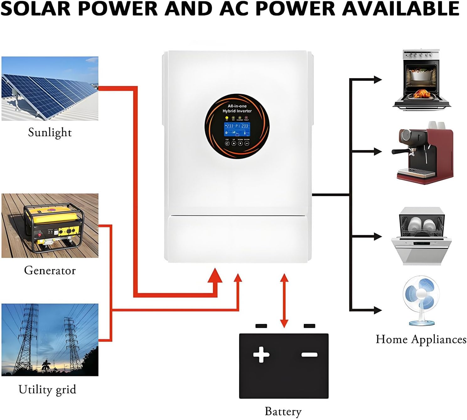
Figure 3.2: System diagram illustrating solar power and AC power availability and flow.
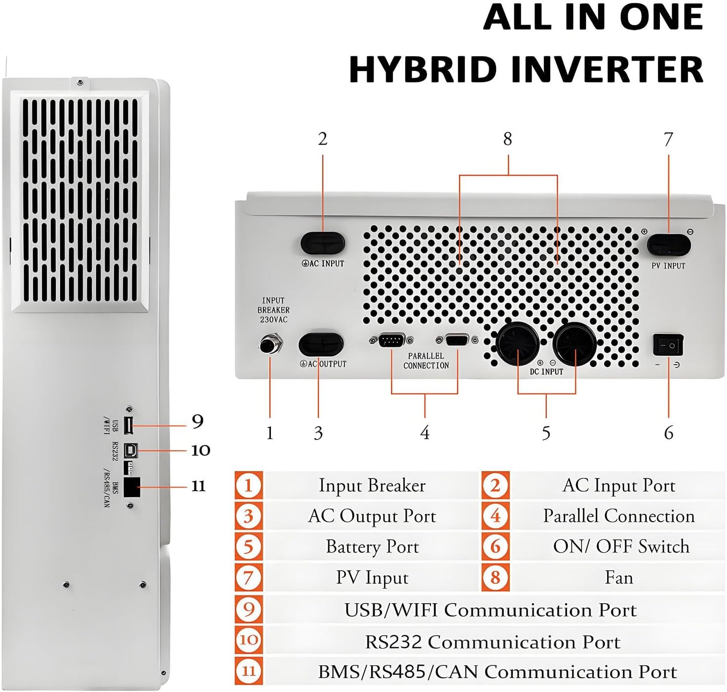
Figure 3.3: Rear Panel Connections and Ports.
- Input Breaker
- AC Input Port
- AC Output Port
- Parallel Connection Port
- Battery Port
- ON/OFF Switch
- PV Input Port
- Fan
- USB/WiFi Communication Port
- RS232 Communication Port
- BMS/RS485/CAN Communication Port
4. Setup and Installation
Proper installation is crucial for the inverter's performance and safety. Follow these steps carefully:
4.1 Site Selection
- Install the inverter in a cool, dry, and well-ventilated area.
- Avoid direct sunlight, high temperatures, and excessive humidity.
- Ensure sufficient clearance around the inverter for proper airflow (refer to Figure 3.3 for fan location).
- Mount the inverter vertically on a sturdy surface.
4.2 Wiring Connections
All wiring must comply with local electrical codes and regulations. Use appropriately sized cables for all connections.
- Battery Connection: Connect the 48V DC battery bank to the Battery Port (5). Ensure correct polarity.
- PV Input Connection: Connect the solar panel array to the PV Input Port (7). Verify the MPPT voltage range (120-500 Vdc) and maximum input power (5500W).
- AC Input Connection: Connect the utility grid or generator to the AC Input Port (2).
- AC Output Connection: Connect your loads (appliances) to the AC Output Port (3).
- Grounding: Ensure the inverter is properly grounded.

Figure 4.1: Parallel Connection Diagram for multiple inverters (up to 8 units).
4.3 Communication Setup
The inverter supports various communication interfaces for monitoring and control:
- USB/WiFi (9): For local or remote monitoring via app/web portal.
- RS232 (10): For PC communication.
- BMS/RS485/CAN (11): For battery management system integration.

Figure 4.2: Remote Monitoring Setup via Computer.
5. Operating Instructions
5.1 Powering On/Off
- To Power On: Ensure all connections are secure. Switch on the battery breaker, then the AC input breaker (if applicable), and finally the inverter's ON/OFF Switch (6).
- To Power Off: Switch off the inverter's ON/OFF Switch (6), then the AC input breaker, and finally the battery breaker.
5.2 LCD Display and Settings
The LCD interface provides real-time data and allows configuration of operating parameters. Navigate using the buttons below the display.

Figure 5.1: LCD Display and Feature Icons.
Key display information includes: Run status, Load percentage, Input voltage, Output voltage, Battery status, and Charging current.
5.3 Operating Modes
The inverter offers flexible operating modes to suit different energy needs:
- Charging Modes:
- PV Priority: Solar power is prioritized for charging.
- Utility Priority: Grid power is prioritized for charging.
- Hybrid Charging: Utilizes both solar and grid power for charging.
- Solar Only Charging: Only solar power is used for charging.
- Output Modes:
- Utility Bypass: Loads are powered directly by the utility grid.
- Inverter Output: Loads are powered by the inverter (from battery or solar).
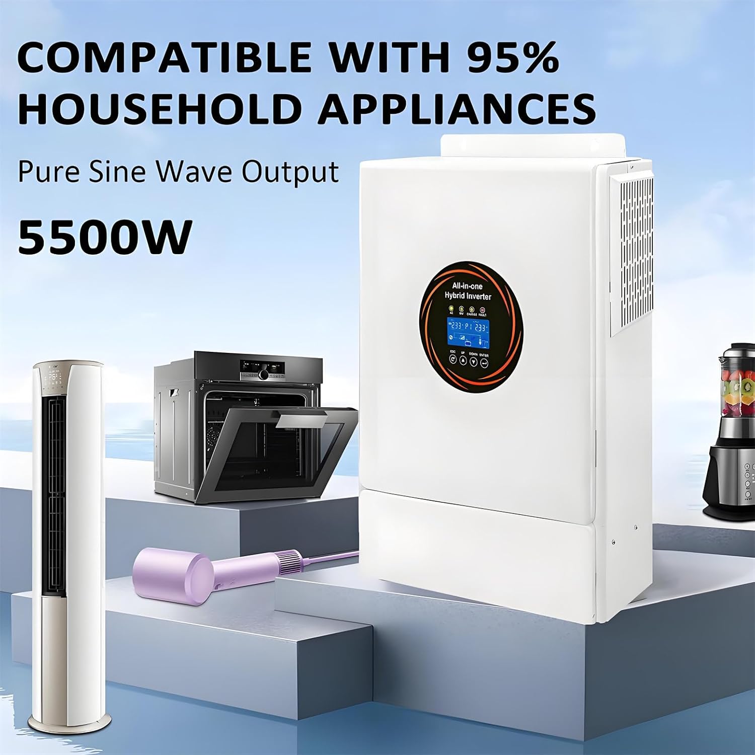
Figure 5.2: Compatibility with Household Appliances.
6. Maintenance
Regular maintenance ensures the longevity and optimal performance of your inverter.
- Cleaning: Periodically clean the exterior of the inverter with a dry cloth. Ensure ventilation openings are free from dust and debris.
- Connections: Regularly check all electrical connections for tightness and signs of corrosion.
- Ventilation: Ensure the area around the inverter remains clear for proper airflow.
- Battery Health: Monitor battery voltage and health, especially for lead-acid batteries. Follow battery manufacturer's maintenance guidelines.
- Firmware Updates: Check the manufacturer's website for any available firmware updates for improved performance or new features.
Caution: Before performing any maintenance, ensure the inverter is completely powered off and disconnected from all power sources (PV, AC, Battery).
7. Troubleshooting
This section provides solutions to common issues you might encounter. For problems not listed here, please contact customer support.
| Problem | Possible Cause | Solution |
|---|---|---|
| Inverter not turning on | No battery connection; Battery voltage too low; ON/OFF switch off; Input breaker tripped. | Check battery connections; Charge battery; Turn ON/OFF switch on; Reset input breaker. |
| No AC output | Overload; Short circuit; Inverter fault; AC output breaker tripped. | Reduce load; Check for short circuits; Contact support if fault persists; Reset AC output breaker. |
| Battery not charging | PV input too low/high; AC input not present; Charge controller fault; Battery fault. | Check PV voltage/current; Verify AC input; Check battery connections; Consult battery manual. |
| Abnormal noise | Loose components; Fan obstruction; Internal fault. | Check for loose parts; Clear fan obstructions; If noise persists, contact support. |
8. Technical Specifications
| Parameter | Value |
|---|---|
| Model | o9sc-878980 |
| Rated Output Power | 5500 W |
| Peak Power | 11000 VA |
| Nominal Input Voltage (AC) | 220/230/240 V AC |
| Input Voltage Range (AC) | 90-280 V AC ±3 V (Normal), 170-280 V AC ±3 V |
| Output Voltage (AC) | 220/230/240 V AC ±5% |
| Output Waveform | Pure Sine Wave |
| Transfer Time | 10 ms (typical) |
| Nominal Battery Voltage | 48 V DC |
| Max. PV Input Power | 5500 W |
| MPPT Voltage Range | 120-500 V DC |
| Max. PV Input Current | 20 A |
| Max. AC Charge Current | 100 A |
| Max. Total Charge Current | 100 A |
| Efficiency (Peak) | > 94% |
| Communication Interfaces | BMS/RS232/RS485/CAN/USB/Dry Contact |
| Parallel Port | Yes (up to 8 units) |
| Noise Level | < 50 dB |
| Dimensions (L*W*H) | 536*352*135 mm |
| Weight | 5 kg |
9. Warranty and Support
For any questions or technical assistance, please contact GYQSSD customer support. We aim to respond to all inquiries within 24 hours.
Please refer to your purchase documentation for specific warranty terms and conditions.
Contact Information:
- Email: [Refer to product packaging or purchase invoice]
- Website: [Refer to product packaging or purchase invoice]
Ask a question about this manual
Ask about setup, troubleshooting, compatibility, parts, safety, or missing instructions. Manuals+ will review the question and use this page’s manual context to help answer it.