1. Introduction
This manual provides essential information for the proper installation, operation, and maintenance of the LDHJBNAC XMTD-3002 CU50 Type Digital Temperature Controller. Please read this manual thoroughly before using the device to ensure safe and efficient operation.
2. Product Overview
The XMTD-3002 CU50 Type is an intelligent digital temperature control instrument designed for precise temperature regulation in various industrial and commercial applications. It features a clear digital display and intuitive controls for setting and monitoring temperature.
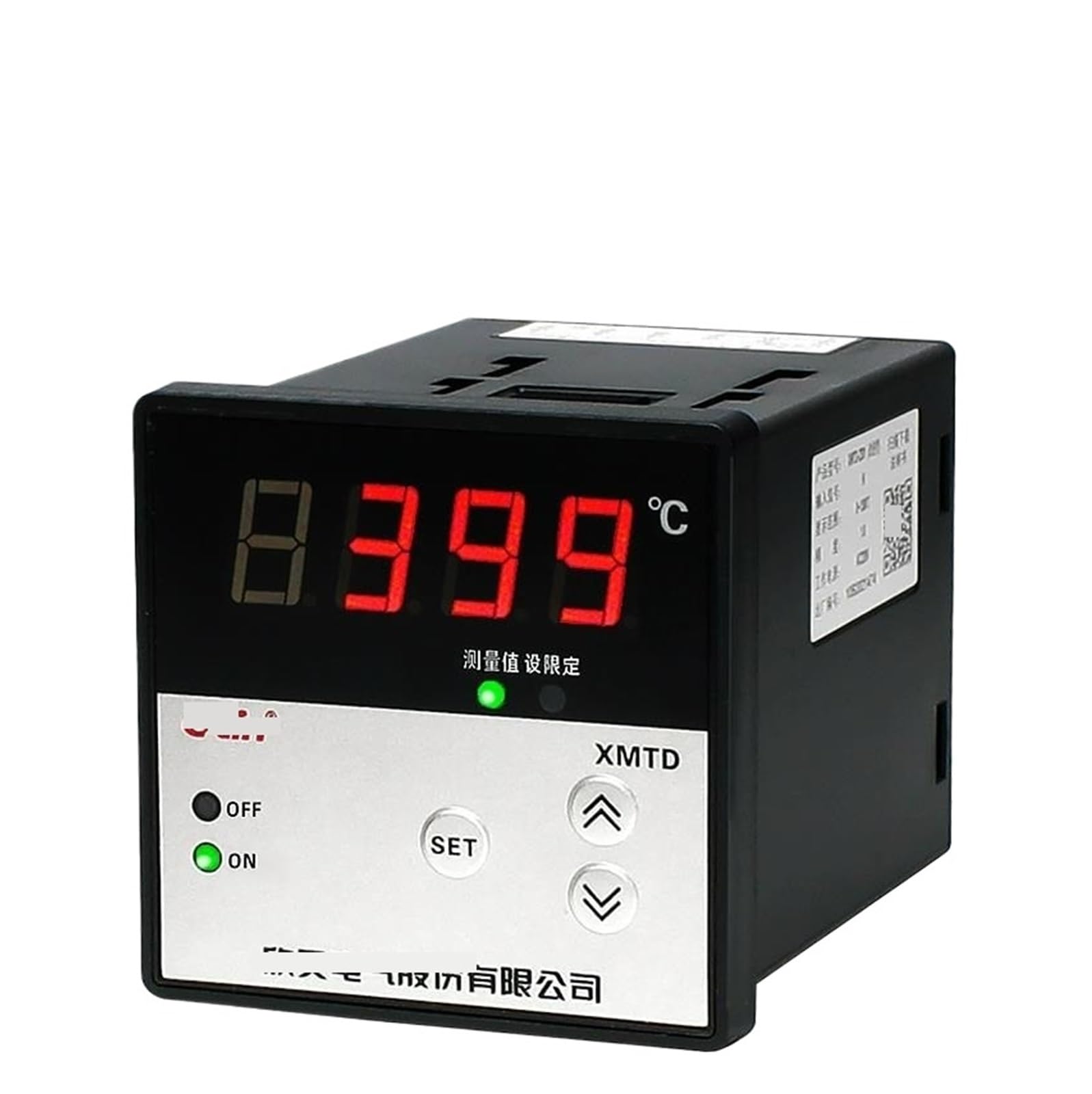
Figure 1: Front view of the XMTD-3002 Digital Temperature Controller. It shows the digital display, 'OFF' and 'ON' indicators, 'SET' button, and up/down arrow buttons for parameter adjustment.

Figure 2: Detailed front panel of the controller, highlighting the digital display for measured value and set value, along with control buttons.
3. Specifications
| Feature | Description |
|---|---|
| Model | XMTD-3002 CU50 Type |
| Input Type | CU50 (RTD) |
| Mounting | Flush Mounting |
| Terminals | Screw Terminals |
| Display | Highly accurate digital display |
| Power Supply | AC 220V (Typical for this series, verify specific unit label) |
Note: Specific display range and accuracy may vary. Refer to the product label on your specific unit for precise details.
4. Setup
4.1 Mounting
The XMTD-3002 controller is designed for flush mounting. Ensure adequate space for ventilation and access to wiring terminals. Secure the controller using the provided mounting brackets.

Figure 3: Side view illustrating the mounting bracket mechanism and a general wiring diagram. The diagram shows connections for both thermocouples and RTDs (thermal resistors).
4.2 Wiring
All wiring should be performed by a qualified electrician in accordance with local electrical codes. Ensure the power supply is disconnected before making any connections.
- Identify the power input terminals (AC 220V).
- Connect the CU50 RTD sensor to the designated input terminals. For CU50 (RTD), typically a three-wire connection is used for compensation. Refer to the wiring diagram on the unit or in Figure 4.
- Connect the control output terminals to your heating or cooling element as required.
- Ensure all screw terminals are tightened securely to prevent loose connections.

Figure 4: Bottom view showing the terminal blocks for XMTD-3001 and XMTD-3002 models. The XMTD-3002 (right side) shows terminals for power input (AC 220V) and sensor/output connections. For CU50 RTD, typically terminals 1, 2, 3 are for the sensor, and 4, 5, 6 for control output.
5. Operating Instructions
5.1 Power On/Off
- To power on the device, ensure all wiring is correct and then connect the main power supply. The 'ON' indicator light will illuminate, and the display will show the current measured temperature.
- To power off, disconnect the main power supply.
5.2 Setting the Temperature (Set Point)
The XMTD-3002 features a simplified operation process for setting the desired temperature.
- Press the SET button once. The display will typically show the current set point, often indicated by a small light next to '设定值' (Set Value).
- Use the Up (↑) and Down (↓) arrow buttons to adjust the set point to your desired temperature.
- Press the SET button again to confirm and save the new set point. The display will return to showing the measured temperature.
5.3 Parameter Adjustment (Advanced Settings)
For advanced parameters such as proportional band, integral time, derivative time, alarm settings, or sensor calibration, a longer press of the SET button (e.g., 3-5 seconds) may be required to enter the parameter setting mode. Consult the specific parameter codes and adjustment procedures provided with your unit, as these can vary.
6. Maintenance
- Cleaning: Keep the controller's front panel clean and free from dust. Use a soft, dry cloth. Do not use abrasive cleaners or solvents.
- Inspection: Periodically check wiring connections for tightness and signs of corrosion or damage.
- Environment: Ensure the operating environment is within the specified temperature and humidity ranges to prolong the life of the device.
7. Troubleshooting
| Problem | Possible Cause | Solution |
|---|---|---|
| No display/No power | No power supply; Loose wiring; Blown fuse (internal/external) | Check power connection; Verify wiring; Check fuse. |
| Incorrect temperature reading | Sensor wiring error; Damaged sensor; Incorrect sensor type selected (if configurable) | Verify sensor wiring (CU50); Replace sensor; Check parameter settings. |
| Controller not heating/cooling | Output wiring error; Damaged heating/cooling element; Set point not reached; Control mode issue | Check output wiring; Test heating/cooling element; Adjust set point; Review control parameters. |
| Display shows 'HHHH' or 'LLLL' | Sensor open circuit (HHHH) or short circuit (LLLL); Temperature out of range | Check sensor and wiring; Replace sensor if damaged. |
8. Warranty and Support
For warranty information and technical support, please refer to the documentation provided with your purchase or contact the manufacturer directly. Keep your purchase receipt for warranty claims.
Manufacturer: LDHJBNAC