MMX-101
NOTIFIER MMX-101 Fire Alarm Addressable Monitor Module
User Manual
1. Introduction
The NOTIFIER MMX-101 is an addressable monitor module designed for use with intelligent fire alarm control panels. It provides a supervised input circuit for monitoring normally open contact devices such as waterflow switches, conventional heat detectors, or pull stations. Each module is individually addressed by rotary switches, allowing the control panel to identify the exact location of an alarm or trouble condition.
2. Safety Information
Important: Installation of this device must be performed by qualified personnel in accordance with all applicable national and local codes and standards, including NFPA 72, National Fire Alarm and Signaling Code. Failure to do so may result in property damage, serious injury, or death.
- Always disconnect power to the fire alarm control panel before installing, servicing, or removing the module.
- Ensure proper grounding and wiring to prevent electrical shock and ensure correct operation.
- Do not exceed the specified electrical ratings for the module.
- Protect the module from moisture and extreme temperatures.
3. Product Overview and Components
The MMX-101 module is a compact device designed for easy integration into various fire alarm system configurations. It typically comes in a protective casing with clearly marked terminals for wiring.

Figure 3.1: Product Packaging
This image shows two retail boxes of the MMX-101 Input Module, indicating the product packaging as it would typically be received.
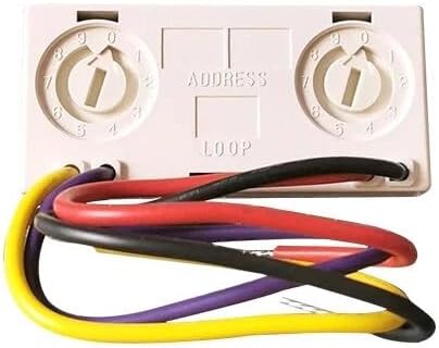
Figure 3.2: MMX-101 Module
This image displays the MMX-101 module itself, featuring two rotary switches for address setting (labeled "ADDRESS" and "LOOP") and various colored wires for connection to the fire alarm control panel and the monitored device.
4. Specifications
| Attribute | Detail |
|---|---|
| Model Number | MMX-101 |
| Manufacturer | China |
| Part Number | ASD-PL |
| Item Weight | 1 pound |
| Power Source | Corded Electric |
| Included Components | Plastics |
5. Installation and Setup
The MMX-101 module is designed for easy installation in a standard 4-inch square electrical box or directly within the device it monitors. Always refer to the specific wiring diagrams provided by NOTIFIER for your fire alarm control panel model.
5.1. Addressing the Module
Each MMX-101 module requires a unique address on the Signaling Line Circuit (SLC) loop. The address is set using the two rotary switches on the module (refer to Figure 3.2). The switches are labeled for tens and units digits. For example, to set address 25, turn the tens switch to '2' and the units switch to '5'.
5.2. Wiring
Connect the module to the SLC loop and the monitored device according to the system's wiring diagram. Ensure all connections are secure and properly insulated. The module typically has terminals for:
- SLC In/Out: Connections to the fire alarm control panel's SLC loop.
- Initiating Device Circuit (IDC): Connections to the normally open contact device being monitored. An End-of-Line Resistor (EOLR) must be installed across the last device on the IDC circuit as specified by the control panel manufacturer.
Note: Incorrect wiring can lead to system malfunctions or false alarms. Consult a qualified fire alarm technician if you are unsure about any wiring procedures.
6. Operation
Once properly installed and addressed, the MMX-101 module continuously monitors the status of the connected initiating device circuit. In a normal state, the module reports a 'normal' status to the fire alarm control panel.
- Alarm Condition: When the connected device (e.g., waterflow switch, pull station) activates, the module detects the change in the IDC circuit (e.g., contact closure) and transmits an alarm signal with its unique address to the fire alarm control panel.
- Trouble Condition: The module also monitors for trouble conditions on the IDC, such as an open circuit (e.g., broken wire) or a short circuit. Upon detecting a trouble condition, it transmits a trouble signal with its unique address to the control panel.
The fire alarm control panel then processes these signals, activating alarms, displaying messages, and initiating other programmed responses as required by the system design.
7. Maintenance
The MMX-101 module is designed for reliable, long-term operation with minimal maintenance. However, regular system inspections and testing are crucial for ensuring the overall integrity of the fire alarm system.
- Visual Inspection: Periodically inspect the module and its wiring for any signs of physical damage, corrosion, or loose connections.
- System Testing: The fire alarm system, including all modules and connected devices, should be tested regularly by qualified personnel in accordance with NFPA 72 and local fire codes. This includes testing the functionality of the monitored devices and verifying that the MMX-101 correctly reports alarm and trouble conditions to the control panel.
- Cleaning: If necessary, gently clean the exterior of the module with a soft, dry cloth. Do not use abrasive cleaners or solvents.
8. Troubleshooting
If the MMX-101 module or the connected device is not functioning as expected, consider the following common issues:
- Module Not Reporting:
- Verify power to the fire alarm control panel.
- Check SLC loop wiring for opens or shorts.
- Ensure the module's address is correctly set and unique on the loop.
- Confirm the module is properly seated in its base (if applicable).
- Trouble Condition on IDC:
- Check wiring to the monitored device for opens, shorts, or ground faults.
- Verify the correct End-of-Line Resistor (EOLR) is installed and properly terminated.
- Test the monitored device itself for proper operation.
- False Alarms:
- Inspect the monitored device for environmental factors (e.g., waterflow switch activation due to pressure fluctuations).
- Check for intermittent wiring issues or loose connections.
For persistent issues, consult the fire alarm control panel's manual or contact a qualified fire alarm technician.
9. Warranty and Support
For information regarding the warranty of the NOTIFIER MMX-101 module, please refer to the warranty statement provided by the manufacturer or your authorized distributor at the time of purchase. Technical support and service should be obtained through your fire alarm system installer or an authorized NOTIFIER service provider.
It is recommended to keep records of all installation, testing, and maintenance activities for your fire alarm system.
Ask a question about this manual
Ask about setup, troubleshooting, compatibility, parts, safety, or missing instructions. Manuals+ will review the question and use this page’s manual context to help answer it.