
1. Product Overview
The ARCHUMI B365M D2VX SI is an M ATX motherboard designed to support 8th and 9th Generation Intel Core i9, i7, i5, i3, Pentium, and Celeron processors using the LGA 1151 socket. It features integrated GBE LAN for network connectivity and an ALC887 7.1 channel sound chip for audio. This motherboard is built with robust materials, including solid-state capacitors and an 8-pin plus 24-pin power connector configuration, ensuring stable performance and longevity.
Key features include:
- LGA 1151 Socket: Compatible with 8th and 9th Gen Intel Core, Pentium, and Celeron CPUs.
- Dual Channel DDR4: Two DDR4 DIMM slots supporting up to 32GB of memory at speeds of 2666, 2400, or 2133 MHz.
- Storage Options: Four Serial ATA III ports and one M.2 slot for high-speed storage devices.
- DVI Output: Integrated DVI port for connecting to displays, suitable for home, design, and gaming applications.
- PCIe Expansion: One PCI Express 3.0 x16 slot and two PCI Express 3.0 x1 slots for expanding with discrete graphics cards, sound cards, or network cards.
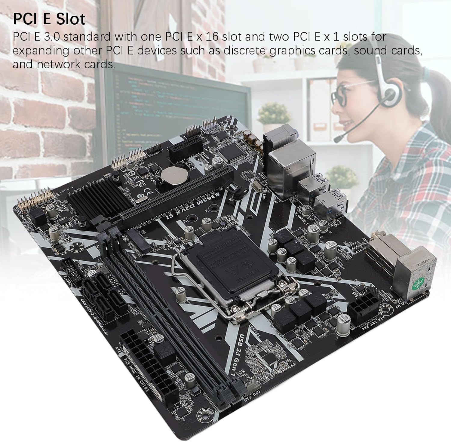
Figure 1.1: Top-down view of the ARCHUMI B365M D2VX SI Motherboard, highlighting the CPU socket, RAM slots, and various connectors.
2. Setup and Installation
Before beginning installation, ensure your workspace is clean and free of static electricity. Use an anti-static wrist strap or frequently touch a grounded metal object to discharge static electricity.
2.1 CPU Installation
- Locate the LGA 1151 socket on the motherboard.
- Gently push down the load lever and pull it to the side to open the CPU socket.
- Align the triangular mark on your Intel processor with the corresponding mark on the socket. Carefully place the CPU into the socket without forcing it.
- Close the load plate and push the load lever back into its locked position.
- Install the CPU cooler according to its manufacturer's instructions.
2.2 Memory (RAM) Installation

Figure 2.1: Close-up view of the two DDR4 memory slots on the ARCHUMI B365M D2VX SI motherboard, illustrating dual-channel capability.
- Locate the two DDR4 DIMM slots on the motherboard.
- Open the clips at both ends of the memory slot.
- Align the notch on the DDR4 memory module with the key in the DIMM slot.
- Insert the memory module firmly into the slot until the clips snap into place. Ensure both clips are fully closed.
2.3 Storage Device Installation
Connect your SATA III storage devices (HDDs/SSDs) to the SATA ports using SATA data cables. For M.2 SSDs, insert the M.2 module into the M.2 slot and secure it with the provided screw.
2.4 Power Supply Connection

Figure 2.2: View of the motherboard's power delivery components, including solid-state capacitors and power connectors, indicating a multi-phase power supply design.
- Connect the 24-pin ATX power connector from your power supply unit (PSU) to the main 24-pin power socket on the motherboard.
- Connect the 8-pin CPU power connector from your PSU to the 8-pin CPU power socket near the CPU.
2.5 Peripheral Connections
- Connect front panel headers (power switch, reset switch, HDD LED, power LED, front USB, front audio) to their respective pins on the motherboard. Refer to the motherboard diagram for correct pin alignment.
- Connect USB devices to the available USB 3.1 Gen 1 and USB 2.0 ports on the rear I/O panel.
- Connect your display to the DVI output port.
- Connect your Ethernet cable to the GBE LAN port for network access.
- Connect audio devices to the 7.1 channel audio ports.

Figure 2.3: Rear I/O panel of the motherboard, clearly showing the DVI output port for display connectivity.
3. Operating Instructions
3.1 Initial Power On
After all components are installed and connected, ensure your power supply is switched on. Press the power button on your computer case. The system should power on, and you should see a display on your monitor.
3.2 BIOS/UEFI Setup
During the initial boot sequence, press the designated key (commonly DEL or F2) to enter the BIOS/UEFI setup utility. Here, you can configure system settings such as boot order, date and time, and enable/disable various integrated peripherals.
3.3 Operating System Installation
Once the BIOS/UEFI settings are configured, you can proceed with installing your preferred operating system (e.g., Windows, Linux). Follow the on-screen instructions provided by your operating system installation media.
4. Maintenance
Regular maintenance helps ensure the longevity and optimal performance of your motherboard and system.
- Dust Removal: Periodically clean dust from inside your computer case, especially from fans and heatsinks, using compressed air. Ensure the system is powered off and unplugged before cleaning.
- Airflow: Ensure proper airflow within your computer case by keeping cables tidy and ensuring case fans are functioning correctly.
- Driver Updates: Keep your motherboard drivers (chipset, LAN, audio) updated to the latest versions available from the ARCHUMI website or your operating system's update service.
- BIOS/UEFI Updates: Only update the BIOS/UEFI if necessary, following the specific instructions provided by ARCHUMI to avoid potential system instability.
5. Troubleshooting
If you encounter issues with your motherboard, consider the following troubleshooting steps:
- No Power:
- Verify that the power supply unit (PSU) is switched on and properly connected to the wall outlet.
- Check that the 24-pin ATX and 8-pin CPU power connectors are securely seated on the motherboard.
- Ensure the front panel power switch cable is correctly connected to the motherboard header.
- No Display:
- Confirm that your monitor is powered on and the DVI cable is securely connected to both the motherboard and the monitor.
- Reseat the RAM modules in their slots. Incorrectly seated RAM is a common cause of no display.
- If using a discrete graphics card, ensure it is properly seated in the PCIe x16 slot and has adequate power connected.

Figure 5.1: View of the PCI Express 3.0 x16 and x1 slots, used for graphics cards and other expansion devices.
- System Instability/Crashes:
- Check for overheating. Ensure CPU cooler and case fans are working.
- Run memory diagnostic tools to check for faulty RAM.
- Ensure all drivers are up to date.
- CMOS Reset: If you experience persistent boot issues or incorrect BIOS settings, you can reset the CMOS (Complementary Metal-Oxide-Semiconductor) to default settings. This typically involves removing the small coin-cell battery (CR2032) from the motherboard for a few minutes while the system is unplugged, or using a dedicated CLR_CMOS jumper if available.
6. Specifications
| Feature | Specification |
|---|---|
| Model | B365M D2VX SI |
| Chipset | Intel B365 High-Speed Chipset |
| CPU Socket | LGA 1151 |
| Supported CPUs | 9th and 8th Gen Intel Core i9/i7/i5/i3, Pentium, Celeron Series Processors |
| Memory Slots | 2 x DDR4 DIMM (Dual Channel) |
| Max Memory Capacity | 32GB |
| Memory Speed Support | DDR4 2666/2400/2133MHz |
| Storage Interfaces | 4 x SATA III, 1 x M.2 Slot |
| PCIe Standard | PCI Express 3.0 |
| PCIe Slots | 1 x PCIe X16, 2 x PCIe X1 |
| Integrated Audio | ALC887 7.1 Channel Sound Chip |
| Integrated LAN | GBE LAN |
| Video Interface | 1 x DVI |
| USB Interfaces (Rear) | 4 x USB 3.1 Gen 1, 2 x USB 2.0/1.1 |
| USB Interfaces (Headers) | 2 x USB 3.1 Gen 1 (via cable), 4 x USB 2.0/1.1 (via cable) |
| Power Connectors | 1 x 8-pin, 1 x 24-pin |
| Other Interfaces | PS/2 Mouse Port, PS/2 Keyboard Port, Ethernet Port, 3 x Audio Ports |
| Form Factor | M ATX |
| Approx. Dimensions (Package) | 28.4 x 25.5 x 6 cm |
7. Warranty and Support
For warranty information, please refer to the documentation included with your purchase or visit the official ARCHUMI website. Warranty terms and conditions may vary by region and retailer.
For technical support, driver downloads, or further assistance, please contact ARCHUMI customer service or the retailer from whom you purchased the product. Keep your proof of purchase handy when seeking support.