1. Introduction
This manual provides essential information for the proper use and integration of the Generic AD142A0 SOP-16 Microcontroller. It covers product overview, setup, operating instructions, maintenance, troubleshooting, and technical specifications. Please read this manual thoroughly before using the device to ensure optimal performance and longevity.
2. Product Overview
The AD142A0 SOP-16 is a microcontroller designed for various embedded applications. It comes in a Small Outline Package (SOP-16) for surface-mount assembly. This component is identified by part numbers AD142A0, AB22BP, and ETA2344, indicating its specific variant and manufacturing details.
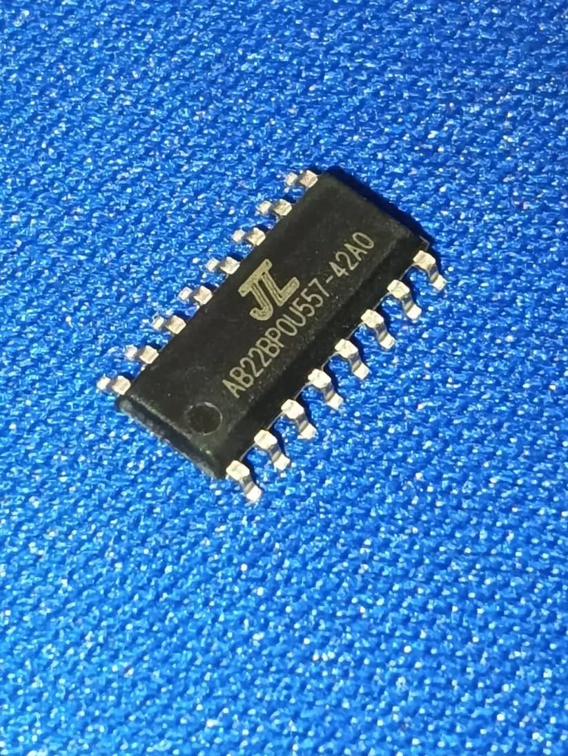
Figure 2.1: AD142A0 SOP-16 Microcontroller. This image displays the compact, rectangular form factor of the SOP-16 package, typically featuring pins extending from two sides for surface mounting onto a printed circuit board.
Included Components:
- 1 x AD142A0 SOP-16 Microcontroller (AB22BP variant)
3. Setup Instructions
Proper setup is crucial for the reliable operation of the AD142A0 microcontroller. This section outlines general guidelines for integration.
- Electrostatic Discharge (ESD) Precautions: Always handle the microcontroller in an ESD-safe environment. Use anti-static wrist straps and mats to prevent damage from static electricity.
- Soldering: The SOP-16 package requires surface-mount soldering. Ensure proper soldering techniques are used to avoid short circuits or cold solder joints. Refer to industry standards for reflow or hand soldering profiles.
- Power Supply: Connect the microcontroller to a stable and regulated power supply within its specified voltage range. Consult the official datasheet for exact voltage requirements and current consumption.
- Pin Connections: Carefully identify the function of each pin (e.g., VCC, GND, I/O, Reset) using the official AD142A0 datasheet. Incorrect connections can lead to permanent damage.
- External Components: Integrate necessary external components such as decoupling capacitors, pull-up/pull-down resistors, and crystal oscillators as recommended in the datasheet for stable operation.
Note: For detailed pinout diagrams and electrical characteristics, always refer to the manufacturer's official datasheet for the AD142A0.
4. Operating Instructions
Operating the AD142A0 microcontroller involves programming and interfacing with other components. The following steps provide a general guide.
- Programming: The microcontroller typically requires firmware to perform specific tasks. Use a compatible Integrated Development Environment (IDE) and a suitable programmer/debugger to load your code onto the chip.
- Interfacing: Connect peripheral devices (sensors, actuators, displays) to the microcontroller's input/output (I/O) pins according to your circuit design and the datasheet's specifications.
- Power On: Once all connections are secure and verified, apply power to the circuit. The microcontroller should execute the loaded program.
- Monitoring and Debugging: During development, use debugging tools or serial communication to monitor the microcontroller's behavior and troubleshoot any issues with your code or hardware.
Consult the programming guide and development tools documentation specific to the JieLi Tech AD142A0 series for detailed programming procedures.
5. Maintenance
The AD142A0 microcontroller is a robust electronic component, but proper care can extend its lifespan and ensure continued performance.
- Environmental Conditions: Operate and store the microcontroller within its specified temperature and humidity ranges. Avoid extreme heat, cold, or moisture.
- Cleanliness: Keep the circuit board and the microcontroller free from dust, dirt, and corrosive substances. Use appropriate cleaning agents for electronics if necessary, ensuring the device is powered off.
- Physical Protection: Protect the assembled circuit from physical shock or excessive vibration.
- ESD Protection: Continue to observe ESD precautions when handling or working near the microcontroller, even after it has been integrated into a circuit.
6. Troubleshooting
If you encounter issues with your AD142A0 microcontroller, consider the following common troubleshooting steps:
| Problem | Possible Cause | Solution |
|---|---|---|
| Microcontroller not powering on/responding. |
|
|
| Program not executing as expected. |
|
|
| Intermittent operation. |
|
|
If these steps do not resolve the issue, consult the official AD142A0 datasheet and programming guides, or seek assistance from the seller or manufacturer.
7. Specifications
| Feature | Detail |
|---|---|
| Model Number | AD142A0 SOP-16 (AB22BP) |
| Brand | Generic |
| Manufacturer | AD142A0 |
| Package Type | SOP-16 |
| Country of Origin | India |
| Item Weight | 100 g |
| Product Dimensions (LxWxH) | 1.9 x 1.5 x 1.5 cm (19 x 15 x 15 Millimeters) |
| Included Components | AD142A0 SOP-16 Microcontrollers AB22BP |
| Batteries Included | No |
| ASIN | B0FKTH6T5H |
| Date First Available | 21 August 2018 |
| Net Quantity | 1 Count |
Note: All specifications are subject to change without prior notice. For the most current and detailed specifications, refer to the official manufacturer's datasheet.
8. Warranty and Support
Warranty Information:
This product is typically covered by a 10-day replacement policy from the date of purchase, as offered by the seller. For specific warranty terms and conditions, including duration and coverage, please contact the seller directly. Manufacturer warranty details for the AD142A0 microcontroller should be obtained from the official JieLi Tech documentation or their authorized distributors.
Technical Support:
For technical assistance, detailed datasheets, programming guides, or inquiries regarding the AD142A0 microcontroller, it is recommended to:
- Refer to the official documentation provided by JieLi Tech.
- Contact the seller: ETSTORE THRISSUR KERALA INDIA
- Contact the packer for general inquiries: e4emerging@gmail.com


