1. Introduction
This manual provides comprehensive instructions for the installation, setup, and operation of the JHEMCU G474 ELRS All-In-One (AIO) Flight Controller. Designed for FPV micro drones, this compact unit integrates a flight controller, Electronic Speed Controller (ESC), and an ELRS 2.4G receiver. Please read this manual thoroughly before use to ensure proper functionality and safety.
2. Product Overview
The JHEMCU G474 ELRS AIO Flight Controller is a high-performance component for FPV drone enthusiasts. It features an STM32G474CE MCU, ICM-42688-P gyroscope, and a 12A 4-in-1 BLHELI_S ESC, all within a compact 25.5x25.5mm mounting footprint.

Figure 2.1: Top and bottom view of the JHEMCU G474 ELRS AIO Flight Controller, showcasing its compact design and integrated components.

Figure 2.2: Detailed diagram indicating the various ports, LEDs, and components on the JHEMCU G474 ELRS AIO Flight Controller, including RX/TX pads, ELRSBOOT button, and antenna socket.
3. Technical Specifications
- MCU: STM32G474CE (170MHz, 512KB Flash)
- Gyro: ICM-42688-P
- Barometer: None
- OSD Chip: AT7456E
- Blackbox: 8MB
- LED Programming: Supported
- Buzzer: Supported
- Input Voltage: 1-2S LiPo
- BEC: 5V / 1.5A, 9V / 2A (for VTX)
- I2C Port: Supported
- Serial Ports (UARTs): UART1 (SBUS), UART2 (VTX), UART3 (Internal ELRS), UART4 (Reserved for GPS/other)
- Flight Controller Firmware: Betaflight 4.5.2 JHEG474.HEX
- ESC Current Rating: 12A x 4
- Current Sensor: Yes
- ESC Firmware: BlueJay Z-H-30.HEX
- Default ESC Protocol: DSHOT600
- Receiver Type: ELRS 2.4G (Internal)
- Receiver Signal Protocol: CRSF
- ELRS Firmware Update: Supports Wi-Fi updating
- Mounting Hole Pattern: M3, 25.5x25.5mm
- Maximum Dimensions: 30x30mm
- Weight: 4.6g
4. What's in the Box
The package for the JHEMCU G474 ELRS AIO Flight Controller typically includes the following components:

Figure 4.1: Included components for the JHEMCU G474 ELRS AIO Flight Controller. This typically includes the flight controller itself, a 220UF/16V capacitor, an IPEX 2.4G antenna, 3P connectors, M2*6.5MM shock-absorbing balls, 20AWGM wire, 1.4*5MM cross screws, and an XT30 connector.
- 1x JHEMCU G474 ELRS AIO Flight Controller
- 1x 220UF/16V Capacitor
- 1x IPEX 2.4G Antenna (gray)
- 4x 3P Connectors
- 4x M2*6.5MM Shock-absorbing Balls
- 2x 20AWGM Wires
- 4x 1.4*5MM Cross Screws
- 1x XT30 Connector
5. Dimensions and Mounting
The JHEMCU G474 ELRS AIO Flight Controller features a compact design suitable for micro drones. Ensure your drone frame has compatible mounting holes.

Figure 5.1: Dimensions of the JHEMCU G474 ELRS AIO Flight Controller. The board measures 30.3mm x 30.3mm, with a mounting hole spacing of 25.5mm x 25.5mm, designed for M3 screws.
The mounting hole pattern is 25.5mm x 25.5mm, compatible with M3 screws. Use the provided shock-absorbing balls to minimize vibrations transferred to the gyroscope.
6. Setup
6.1 Wiring Diagrams
Carefully follow the wiring diagrams below for connecting motors, battery, camera, and video transmitter (VTX). Ensure all connections are secure and correctly polarized.

Figure 6.1: Wiring connections for the JHEMCU G474 ELRS AIO. This diagram illustrates how to connect the 1-2S LiPo battery, camera, motors (Motor1-Motor4), and an optional external SBUS receiver.

Figure 6.2: Wiring connections for video transmitters. This diagram shows how to connect either an HD Digital VTX or a 5.8GHz Analog VTX to the flight controller, utilizing the dedicated VTX pads and UART2 for VTX signal.
6.2 Firmware Flashing
The flight controller comes pre-flashed with Betaflight 4.5.2 (JHEG474.HEX) and the ESCs with BlueJay Z-H-30.HEX. For firmware updates or initial setup, connect the flight controller to your computer via USB. Use the Betaflight Configurator for the flight controller and a compatible ESC configurator (e.g., BlueJay Configurator) for the ESCs.
To flash the flight controller into DFU mode, press and hold the Flight Controller BOOT button while connecting the USB cable.
The internal ELRS receiver supports Wi-Fi updating of its firmware. Refer to the official ELRS documentation for detailed instructions on Wi-Fi firmware updates.
6.3 Initial Power-Up Considerations
When using a 1S battery, you may encounter difficulties starting the motors. This is due to the lower voltage providing less initial torque. To resolve this, increase the starting power value in your ESC settings (e.g., BlueJay Configurator) to a level that allows the motors to spin up reliably.
7. Operating
Once the flight controller is wired and configured, connect your LiPo battery. The Red LED indicates 3.3V power, the Blue LED indicates flight controller status, and the Green LED indicates ELRS status. An Orange LED indicates 9V BEC status.
The integrated ELRS 2.4G receiver operates on the CRSF protocol. Ensure your ELRS transmitter module is bound to the receiver. The ELRSBOOT button can be used for receiver firmware flashing.
The 9V/2A BEC boost circuit provides stable 9V output for the VTX, preventing screen blackouts when using high-definition VTX systems with 2S power supplies.
8. Maintenance
Due to the high integration of the PCB, the solder pads are small. Exercise caution and precision during any soldering work. Ensure proper soldering techniques to avoid short circuits or damage to components.
Regularly inspect all wiring for signs of wear or damage. Keep the flight controller clean and free from dust or debris. Avoid exposing the unit to moisture or extreme temperatures.
9. Troubleshooting
9.1 Motors Not Starting on 1S Battery
Issue: Motors fail to spin up or stutter when using a 1S LiPo battery.
Solution: This is a common issue with 1S setups due to lower voltage. Access your ESC configuration software (e.g., BlueJay Configurator) and increase the 'Starting Power' value. Adjust incrementally until motors start reliably. Refer to Figure 9.1 for an example of ESC settings.
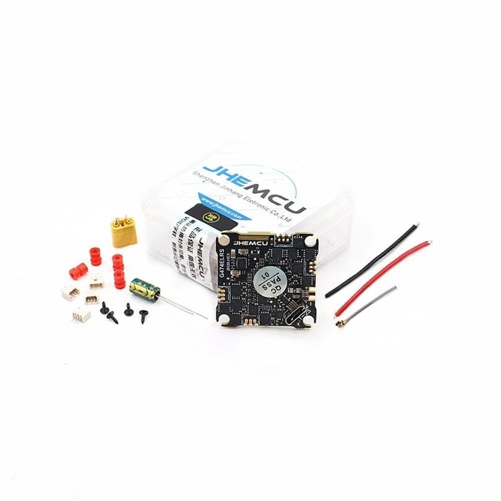
Figure 9.1: Example of BlueJay ESC settings interface. The 'Starting Power' value (highlighted) can be adjusted to address motor startup issues, especially with 1S batteries.
9.2 No Video Signal
Issue: No video feed from the camera or VTX.
Solution: Verify all camera and VTX wiring connections according to Figure 6.2. Ensure the VTX is powered correctly (9V BEC output). Check VTX settings and channel in your Betaflight OSD. Confirm that UART2 is correctly configured for VTX telemetry if applicable.
9.3 ELRS Receiver Not Binding
Issue: The internal ELRS receiver does not bind with the ELRS transmitter module.
Solution: Ensure both the flight controller and transmitter module are running compatible ELRS firmware versions. Check the binding phrase. Use the ELRSBOOT button to put the receiver into binding mode if necessary, or use the Wi-Fi update method to re-flash the receiver firmware.
10. Warranty Information
This product is intended for advanced users with soldering and FPV drone building experience. Due to the nature of DIY electronics and the high integration of components, warranty coverage may be limited. Please contact your retailer or the manufacturer for specific warranty terms and conditions.
11. Support
For further technical assistance, firmware updates, or community support, please refer to the official JHEMCU website, Betaflight documentation, and ELRS project resources. Online FPV forums and communities can also provide valuable troubleshooting advice and setup guides.