Introduction
The Zoyi ZT-102 is a compact and versatile digital multimeter designed for accurate measurement of various electrical parameters. This manual provides essential information for the safe and effective use of your device, including setup, operation, maintenance, and troubleshooting.
Package Contents
Please check the package carefully to ensure all items are present and undamaged. If any items are missing or damaged, contact your retailer.
- 1 x Zoyi ZT-102 Digital Multimeter
- 2 x Measurement Probe Cables (Red and Black)
- 1 x Temperature Measurement Cable
- 2 x AAA Batteries
- 1 x Gray Carrying Bag
- 1 x User Manual (this document)
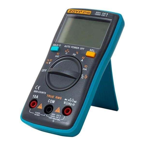
Image: Zoyi ZT-102 Digital Multimeter with its included test probes and temperature probe.

Image: The Zoyi ZT-102 Digital Multimeter, its retail packaging, and the gray carrying bag.
Product Features and Specifications
The Zoyi ZT-102 Digital Multimeter offers a range of measurement capabilities for various electrical applications.
| Feature | Specification |
|---|---|
| Voltage Measurement (AC) | Maximum 750 V |
| Voltage Measurement (DC) | Maximum 1000 V |
| Current Measurement (DC) | Maximum 10 A |
| Current Measurement (AC) | Maximum 10 A |
| Resistance Measurement | Maximum 60 MΩ |
| Capacitance Measurement | Maximum 9.999 mF |
| Frequency Measurement | Maximum 9.999 MHz |
| Duty Cycle | Supported |
| Continuity Test | Supported |
| Diode Test | Supported |
| Temperature Measurement | -20℃ to 1000℃ / -4℉ to 1832℉ |
| Power Source | 2 x AAA Batteries (included) |
Safety Information
To ensure safe operation and avoid damage to the meter, please read and follow all safety instructions carefully.
- Always ensure the meter is in the correct function and range before making measurements.
- Do not exceed the maximum input values for any range.
- Exercise extreme caution when working with voltages above 30V AC RMS, 42V peak, or 60V DC. These voltages pose a shock hazard.
- Disconnect test leads from the circuit before changing functions or ranges.
- Do not use the meter if it appears damaged or if the insulation on the test leads is compromised.
- Replace batteries immediately when the low battery indicator appears to ensure accurate readings.
- Do not operate the meter in explosive gas, vapor, or dusty environments.
- Always use the appropriate input terminals for the measurement being performed.
Setup
1. Battery Installation
The Zoyi ZT-102 requires two AAA batteries for operation. These are included in your package.
- Ensure the multimeter is turned OFF.
- Locate the battery compartment cover on the back of the device.
- Use a screwdriver to loosen the screw(s) securing the cover.
- Remove the cover and insert the two AAA batteries, observing the correct polarity (+ and -) as indicated inside the compartment.
- Replace the battery compartment cover and tighten the screw(s).
2. Connecting Test Leads
Proper connection of test leads is crucial for accurate and safe measurements.
- Insert the black test lead into the "COM" (Common) input jack.
- For most voltage, resistance, continuity, diode, capacitance, and frequency measurements, insert the red test lead into the "VΩHz" input jack.
- For current measurements (up to 10A), insert the red test lead into the "10A" input jack.
- For temperature measurements, connect the temperature probe to the "VΩHz" and "COM" jacks, observing polarity if applicable (refer to probe markings).
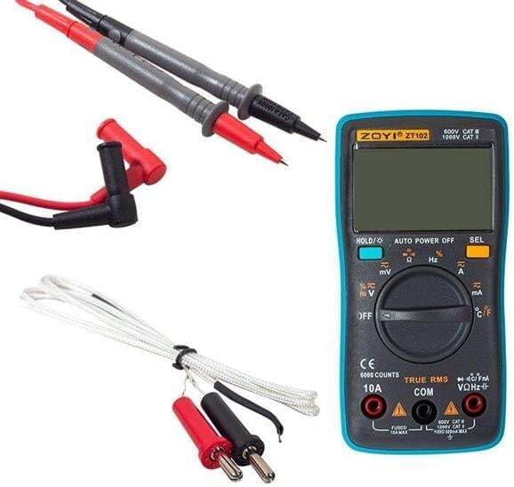
Image: The Zoyi ZT-102 Multimeter with test leads connected to the input jacks.
Operating Instructions
The Zoyi ZT-102 features an automatic ranging function, simplifying operation. Turn the rotary switch to select the desired measurement function.
1. Voltage Measurement (AC/DC)
- Connect the red test lead to the "VΩHz" jack and the black test lead to the "COM" jack.
- Turn the rotary switch to the "V~" (AC Voltage) or "V-" (DC Voltage) position. The meter will automatically select the appropriate range.
- Connect the test probes in parallel across the component or circuit to be measured.
- Read the voltage value on the display.
2. Current Measurement (AC/DC)
Caution: Never connect the meter in parallel across a voltage source when measuring current, as this can damage the meter and pose a safety risk. Always connect in series with the load.
- For currents up to 10A: Connect the red test lead to the "10A" jack and the black test lead to the "COM" jack.
- Turn the rotary switch to the "A~" (AC Current) or "A-" (DC Current) position.
- Open the circuit where current is to be measured and connect the meter in series with the load.
- Read the current value on the display.
3. Resistance Measurement
Caution: Ensure the circuit is de-energized and all capacitors are discharged before measuring resistance.
- Connect the red test lead to the "VΩHz" jack and the black test lead to the "COM" jack.
- Turn the rotary switch to the "Ω" (Resistance) position.
- Connect the test probes across the component whose resistance is to be measured.
- Read the resistance value on the display.
4. Capacitance Measurement
Caution: Ensure capacitors are fully discharged before measurement to prevent damage to the meter.
- Connect the red test lead to the "VΩHz" jack and the black test lead to the "COM" jack.
- Turn the rotary switch to the "F" (Capacitance) position.
- Connect the test probes across the capacitor.
- Read the capacitance value on the display.
5. Frequency and Duty Cycle Measurement
- Connect the red test lead to the "VΩHz" jack and the black test lead to the "COM" jack.
- Turn the rotary switch to the "Hz" (Frequency) position.
- Connect the test probes across the signal source.
- The display will show the frequency. Press the "SEL" button to toggle to Duty Cycle measurement if available.
6. Continuity Test
Caution: Ensure the circuit is de-energized before performing a continuity test.
- Connect the red test lead to the "VΩHz" jack and the black test lead to the "COM" jack.
- Turn the rotary switch to the "Ω" (Resistance) position, then press the "SEL" button until the continuity symbol (a speaker icon) appears on the display.
- Connect the test probes across the component or wire.
- If continuity exists (low resistance), the meter will emit an audible beep.
7. Diode Test
Caution: Ensure the diode is disconnected from the circuit before testing.
- Connect the red test lead to the "VΩHz" jack and the black test lead to the "COM" jack.
- Turn the rotary switch to the "Ω" (Resistance) position, then press the "SEL" button until the diode symbol (a triangle with a line) appears on the display.
- Connect the red probe to the anode and the black probe to the cathode of the diode. The display will show the forward voltage drop.
- Reverse the probes. The display should show "OL" (Open Line) for a good diode.
8. Temperature Measurement
- Connect the temperature measurement cable to the "VΩHz" and "COM" jacks.
- Turn the rotary switch to the "℃/℉" (Temperature) position.
- Place the tip of the temperature probe on or near the object whose temperature is to be measured.
- Read the temperature value on the display. Press the "SEL" button to switch between Celsius (℃) and Fahrenheit (℉).
Maintenance
1. Cleaning
Wipe the meter with a damp cloth and mild detergent. Do not use abrasives or solvents. Ensure the meter is completely dry before use.
2. Battery Replacement
When the low battery indicator appears on the display, replace the batteries as described in the "Battery Installation" section under Setup. Always use two new AAA batteries of the same type.
3. Fuse Replacement
If the current measurement function stops working, the fuse may need replacement. This procedure should only be performed by qualified personnel. Refer to the internal markings for fuse specifications. Always replace with a fuse of the identical type and rating.
Troubleshooting
If you encounter issues with your Zoyi ZT-102, refer to the following common problems and solutions:
- Meter does not turn on: Check battery installation and ensure batteries are fresh.
- No reading or "OL" (Overload) displayed:
- Ensure test leads are correctly inserted into the appropriate jacks.
- Verify the rotary switch is set to the correct function.
- For resistance/continuity, ensure the circuit is de-energized.
- For current, ensure the meter is connected in series and the fuse is intact.
- The measured value might be outside the meter's range.
- Inaccurate readings:
- Check battery level; low batteries can affect accuracy.
- Ensure test leads are making good contact.
- Verify the correct function and range are selected.
- Environmental factors (temperature, humidity) can sometimes affect sensitive measurements.
- Continuity test does not beep: Ensure the function is correctly selected (speaker icon on display) and the circuit is de-energized.
If problems persist, contact customer support or a qualified technician.
Warranty and Support
Warranty information for the Zoyi ZT-102 Digital Multimeter is not available in the product specifications provided. For support or service inquiries, please contact your point of purchase or the manufacturer directly.
Disposal Information
This product contains electronic components and batteries. Do not dispose of it with general household waste. Please follow local regulations for the proper disposal of electronic waste and batteries to protect the environment.
Look for recycling facilities in your area or contact your local authorities for guidance on proper disposal methods.