1. Introduction
This manual provides essential information for the safe and efficient operation, installation, and maintenance of the FPBIGCHA JR100-1.5KW-220V Variable Frequency Drive (VFD). This device is designed for precise motor speed control, particularly in CNC machine tool applications. Please read this manual thoroughly before installation and operation to ensure proper use and to prevent damage or injury.
2. Safety Information
Always observe the following safety precautions to prevent electric shock, fire, or personal injury. Failure to comply with these instructions may result in severe consequences.
- Electrical Hazard: This device operates at high voltage. Only qualified personnel should perform installation, wiring, and maintenance.
- Power Disconnection: Always disconnect all power sources before performing any work on the VFD. Wait for the capacitor discharge indicator to turn off before touching any internal components.
- Grounding: Ensure the VFD is properly grounded according to local electrical codes.
- Environment: Install the VFD in a clean, dry, and well-ventilated area, away from direct sunlight, corrosive gases, flammable materials, and excessive vibration.
- Overload Protection: Do not exceed the rated current or power of the VFD and the connected motor.
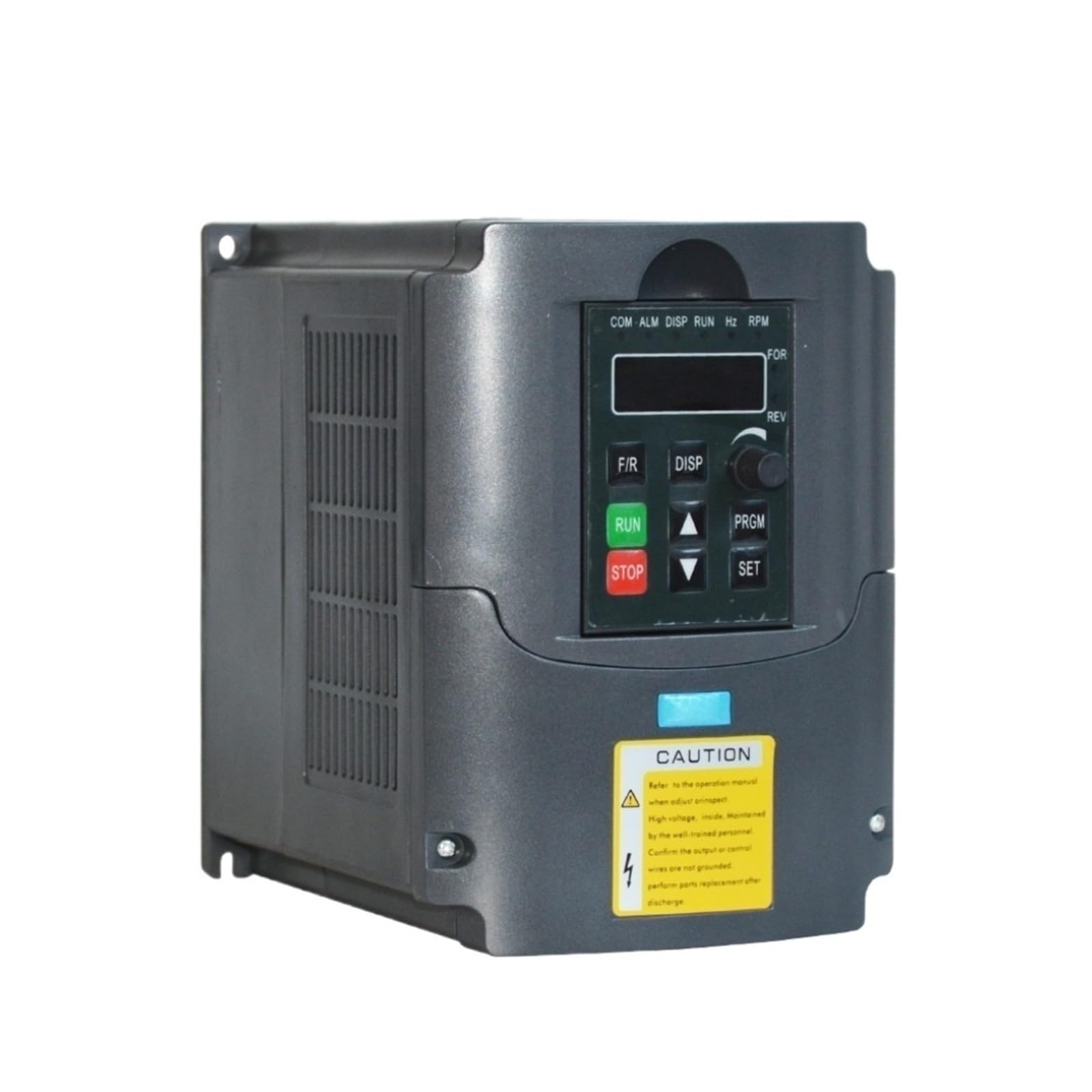
Image 1: Front view of the JR100-1.5KW-220V Variable Frequency Drive, showing its control panel, caution label, and overall dimensions. The caution label indicates high voltage and the need to refer to the operation manual. Dimensions are marked as 170mm (height), 163mm (width), and 125mm (depth).
3. Product Overview
3.1. Features
- Compact size and simple structure for easy integration.
- Sufficient cooling space between electronic components and chassis for effective heat dissipation.
- Designed for motor speed control in CNC machine tools.
- Easy to install and dismantle.
- Connection ports are accessible after removing the front panel.
3.2. Components
The VFD consists of a main power unit, a control circuit, and a user interface. Key components include:
- Control Panel: Features a digital display, function buttons (RUN, STOP, SET, DISP, PRGM, FR, REV), and a rotary knob for parameter adjustment.
- Heat Sink: Integrated for thermal management.
- Wiring Terminals: Located internally for power input, motor output, and control signals.
4. Setup
4.1. Unpacking and Inspection
Carefully remove the VFD from its packaging. Inspect the unit for any signs of physical damage during transit. Report any damage to your supplier immediately.
4.2. Mounting
Mount the VFD vertically on a stable, non-flammable surface. Ensure adequate clearance around the unit for proper ventilation and heat dissipation. Refer to Image 1 for physical dimensions: 170mm (height), 163mm (width), and 125mm (depth).
4.3. Wiring Connections
All wiring must be performed by a qualified electrician. Ensure all power is disconnected before making any connections.
- Power Input (L1, L2): Connect the 220V AC power supply to the designated input terminals.
- Motor Output (U, V, W): Connect the three-phase motor leads to the corresponding output terminals.
- Grounding (PE): Connect the VFD to a reliable earth ground using the designated grounding terminal.
- Control Terminals: If external control signals (e.g., start/stop, speed reference) are used, connect them to the appropriate control terminals as per the wiring diagram (refer to the full product manual for detailed diagrams).
5. Operating Instructions
5.1. Control Panel Overview
The VFD features a user-friendly control panel for monitoring and operation:
- Digital Display: Shows operating status, frequency, current, voltage, and parameter values.
- RUN Button: Initiates motor operation.
- STOP Button: Halts motor operation.
- SET Button: Enters parameter setting mode or confirms a parameter value.
- DISP Button: Toggles between different display parameters.
- PRGM Button: Accesses the parameter menu.
- FR/REV Buttons: Used for forward/reverse direction control (if configured).
- Up/Down Arrows (or Rotary Knob): Adjusts frequency, parameter values, or navigates menus.
5.2. Powering On/Off
- Power On: After ensuring all connections are secure, apply main power to the VFD. The digital display will illuminate.
- Power Off: Press the STOP button to halt the motor, then disconnect the main power supply.
5.3. Basic Operation
- Start Motor: Press the RUN button. The motor will accelerate to the set frequency.
- Stop Motor: Press the STOP button. The motor will decelerate and stop.
- Adjust Speed: Use the Up/Down arrow buttons or the rotary knob to increase or decrease the output frequency, thereby adjusting motor speed.
5.4. Parameter Settings
To access and modify parameters:
- Press the PRGM button to enter the parameter menu.
- Use the Up/Down arrows to navigate through parameter groups or individual parameters.
- Press SET to select a parameter or enter its editing mode.
- Use the Up/Down arrows to change the parameter value.
- Press SET again to save the new value.
- Press PRGM to exit the parameter menu.
Refer to the detailed parameter list in the complete product manual for specific parameter functions and ranges.
6. Maintenance
Regular maintenance ensures the longevity and reliable operation of your VFD.
- Cleaning: Periodically clean the VFD's exterior and ventilation openings to prevent dust accumulation, which can hinder heat dissipation. Use a soft, dry cloth. Do not use liquid cleaners.
- Inspection: Regularly check all wiring connections for tightness and signs of wear or damage. Inspect the cooling fan for proper operation and obstructions.
- Environment: Ensure the operating environment remains within specified temperature and humidity ranges.
- Storage: If storing the VFD for an extended period, keep it in a dry, dust-free environment within the recommended storage temperature range.
7. Troubleshooting
This section provides solutions for common issues. For complex problems, contact technical support.
| Problem | Possible Cause | Solution |
|---|---|---|
| VFD does not power on | No input power; Blown fuse | Check power supply; Inspect and replace fuse if necessary (by qualified personnel). |
| Motor does not run | Incorrect wiring; Parameter settings; Emergency stop active | Verify motor wiring; Check relevant parameters (e.g., run command source); Reset emergency stop. |
| Overcurrent fault | Motor overload; Short circuit in motor wiring; Incorrect acceleration time | Reduce motor load; Check motor and wiring for shorts; Increase acceleration time parameter. |
| Overvoltage fault | High input voltage; Rapid deceleration; Regenerative load | Check input voltage; Increase deceleration time parameter; Consider adding a braking resistor. |
| Overheat fault | Insufficient ventilation; Ambient temperature too high; Fan failure | Ensure proper airflow; Reduce ambient temperature; Check cooling fan operation. |
8. Specifications
Technical specifications for the JR100-1.5KW-220V Variable Frequency Drive:
| Specification | Value |
|---|---|
| Model Number | JR100-1.5KW-220V |
| Rated Power | 1.5 KW |
| Input Voltage | 220V AC |
| Output Voltage | 0-220V AC (adjustable) |
| Output Frequency | 0-400 Hz (adjustable) |
| Control Method | V/F control |
| Cooling Method | Forced air cooling |
| Package Dimensions | 0.39 x 0.39 x 0.39 inches (approximate shipping dimensions) |
| Item Weight | 4.41 pounds |
| Manufacturer | FPBIGCHA |
9. Warranty and Support
9.1. Warranty Information
This product is covered by a manufacturer's warranty against defects in materials and workmanship. The specific terms and duration of the warranty may vary. Please retain your proof of purchase for warranty claims. The warranty does not cover damage caused by improper installation, misuse, unauthorized modifications, or natural disasters.
9.2. Customer Support
For technical assistance, troubleshooting beyond the scope of this manual, or warranty inquiries, please contact your supplier or the manufacturer directly. Provide your product model number and a detailed description of the issue when seeking support.