1. Product Overview
The ZLYMTXHW SVP-63A-220V is a single-phase adjustable self-restoring intelligent current-limiting over-voltage and under-voltage protector. It features an LED dual display for real-time voltage and current monitoring and an automatic reset function. This device is designed to protect electrical equipment from damage caused by voltage fluctuations.
It is suitable for single-phase AC voltage systems of 230V, 50/60Hz, with a rated operating current of 63A or below. Its primary application is for residential sub-box incoming lines or single-phase electrical equipment requiring protection against overvoltage, undervoltage, or overcurrent conditions.
The protector automatically disconnects the power supply when voltage or current anomalies are detected and restores power once conditions return to normal, safeguarding connected appliances.
2. Key Features
- Single-Phase Protection: Designed for 230V AC single-phase systems.
- Adjustable Protection Values: Overvoltage and undervoltage thresholds can be set.
- Current-Limiting Function: Provides protection against overcurrent conditions.
- Automatic Reset: Automatically restores power after fault conditions clear.
- LED Dual Display: Shows real-time voltage and current readings.
- Fast Response: Instantly cuts off power to protect equipment during anomalies.
- Delay Recovery: Adjustable delay time for power restoration after a fault.
3. Specifications
| Model | SVP-63A-220V |
| Rated Voltage | 230V AC |
| Rated Current | 63A |
| Overvoltage Protection Range | 230V ~ 300V (Adjustable) |
| Undervoltage Protection Range | 145V ~ 210V (Adjustable) |
| Failure Recovery Delay Time | 3 ~ 300 seconds (Default: 60 seconds) |
| Package Dimensions | 0.39 x 0.39 x 0.39 inches |
| Item Weight | 1.76 ounces |
Note: All specifications are subject to change without prior notice.
4. Setup and Installation
Important Safety Information: Installation should only be performed by a qualified electrician. Ensure the main power supply is disconnected before beginning any installation work to prevent electric shock.
The SVP-63A-220V protector is designed for DIN rail mounting within an electrical distribution box.
4.1 Wiring Diagram
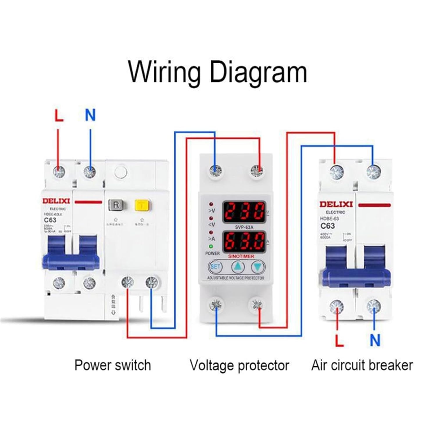
Image Description: This image displays a wiring diagram for the SVP-63A-220V protector. It illustrates the connection sequence: a power switch (left), the SVP-63A voltage protector (center), and an air circuit breaker (right). The diagram shows the Line (L) and Neutral (N) connections, with red wires typically indicating Line and blue wires indicating Neutral, flowing through each component. The voltage protector is positioned between the power switch and the air circuit breaker, indicating its role in monitoring and protecting the circuit before the final load protection.
- Power Disconnection: Before installation, ensure the main power supply to the circuit is completely turned off.
- Mounting: Mount the SVP-63A-220V protector onto a standard DIN rail within your electrical panel.
- Input Connection: Connect the incoming Line (L) and Neutral (N) wires from the power source (or upstream power switch) to the "IN" terminals of the protector. Refer to the wiring diagram for correct polarity.
- Output Connection: Connect the "OUT" terminals of the protector to the input of your load or downstream air circuit breaker. Ensure correct Line (L) and Neutral (N) connections.
- Secure Connections: Tighten all terminal screws securely to prevent loose connections, which can cause overheating or malfunction.
- Verification: Double-check all wiring against the diagram before restoring power.
4.2 Dimensions

Image Description: This image provides a dimensional drawing of the SVP-63A-220V protector. The left side shows the front view with a width of 36mm and a height of 85mm. The right side shows a side view with a depth of 65mm, and a mounting height of 45mm from the DIN rail, with the top section being 36mm high. These measurements are crucial for proper installation and space planning within an electrical enclosure.
5. Operating Instructions
After successful installation and power restoration, the protector will display the current voltage and current on its LED screen.
5.1 Initial Power-Up
- Once power is supplied, the device will perform a self-check and display the current voltage and current.
- If the voltage and current are within the set safe parameters, the protector will automatically connect the output after the recovery delay time.
5.2 Setting Protection Parameters
The SVP-63A-220V allows adjustment of overvoltage, undervoltage, and recovery delay time. Specific button functions (e.g., "SET" button, up/down arrows) are typically used for this. Refer to the device's front panel for button labels.
- Accessing Settings: Press and hold the "SET" button (or equivalent) to enter programming mode. The display will typically flash, indicating that a parameter can be adjusted.
- Adjusting Values: Use the up (<) and down (>) buttons to increase or decrease the displayed value (e.g., overvoltage threshold, undervoltage threshold, or delay time).
- Saving Settings: Press the "SET" button again to confirm and save the adjusted value and move to the next parameter, or wait for the device to automatically exit programming mode after a few seconds of inactivity.
- Overvoltage Protection Range: Adjustable from 230V to 300V.
- Undervoltage Protection Range: Adjustable from 145V to 210V.
- Recovery Delay Time: Adjustable from 3 to 300 seconds. The default is 60 seconds.
5.3 Protection and Automatic Reset
- If the measured voltage exceeds the set overvoltage threshold or drops below the undervoltage threshold, the protector will immediately cut off the power output.
- The LED display will indicate the fault condition (e.g., flashing voltage, specific error code).
- Once the voltage returns to within the safe operating range, the protector will wait for the set recovery delay time to elapse.
- After the delay, the protector will automatically restore power to the output.
6. Maintenance
The SVP-63A-220V protector is designed for reliable operation with minimal maintenance. However, periodic checks are recommended to ensure optimal performance and safety.
- Visual Inspection: Periodically inspect the device for any signs of physical damage, discoloration, or loose connections.
- Cleaning: Keep the device free from dust and debris. Use a dry, soft cloth for cleaning. Do not use liquid cleaners.
- Connection Check: Ensure all wiring connections remain tight and secure. Loose connections can lead to overheating and potential hazards.
- Functionality Test: If possible and safe to do so, periodically test the protection functions by simulating an over/under voltage condition (e.g., using a variable power supply, if available and safe).
Warning: Always disconnect the main power supply before performing any maintenance or inspection to avoid electric shock.
7. Troubleshooting
If the protector is not functioning as expected, refer to the following common issues and solutions:
| Problem | Possible Cause | Solution |
|---|---|---|
| No display/No power | No input power; incorrect wiring; device failure. | Check main power supply. Verify input wiring (L and N). If power is present and wiring is correct, the device may be faulty. |
| Protector trips frequently | Voltage fluctuations in the line; protection thresholds set too sensitive; actual over/under voltage conditions. | Monitor line voltage to confirm stability. Adjust overvoltage/undervoltage thresholds if necessary (within safe limits). Consult an electrician to check the power supply quality. |
| Does not reset automatically | Fault condition persists; recovery delay time not elapsed; device malfunction. | Ensure the line voltage has returned to normal and remained stable for the set recovery delay time. Check delay time settings. If the issue persists, the device may require service. |
| Incorrect voltage/current reading | Sensor issue; display malfunction. | Compare readings with a calibrated multimeter. If readings are consistently inaccurate, the device may be faulty. |
For issues not listed here or if troubleshooting steps do not resolve the problem, please contact customer support or a qualified electrician.
8. Warranty and Support
For warranty information and technical support, please refer to the documentation provided at the time of purchase or contact your vendor. Keep your purchase receipt as proof of purchase.
Manufacturer: ZLYMTXHW
Date First Available: July 26, 2025