1. Introduction
This manual provides essential instructions for the safe and effective use of the AAXTUVCL CB180 Automatic Voltage Regulator (AVR). The CB180 is designed to maintain a stable output voltage for auxiliary engine generator sets, ensuring consistent power delivery. Please read this manual thoroughly before installation and operation.
2. Product Overview
2.1 Features
- Automatic Voltage Regulation for stable power output.
- Specifically designed for auxiliary engine generator sets.
- Integrated electric controls for precise operation and voltage management.
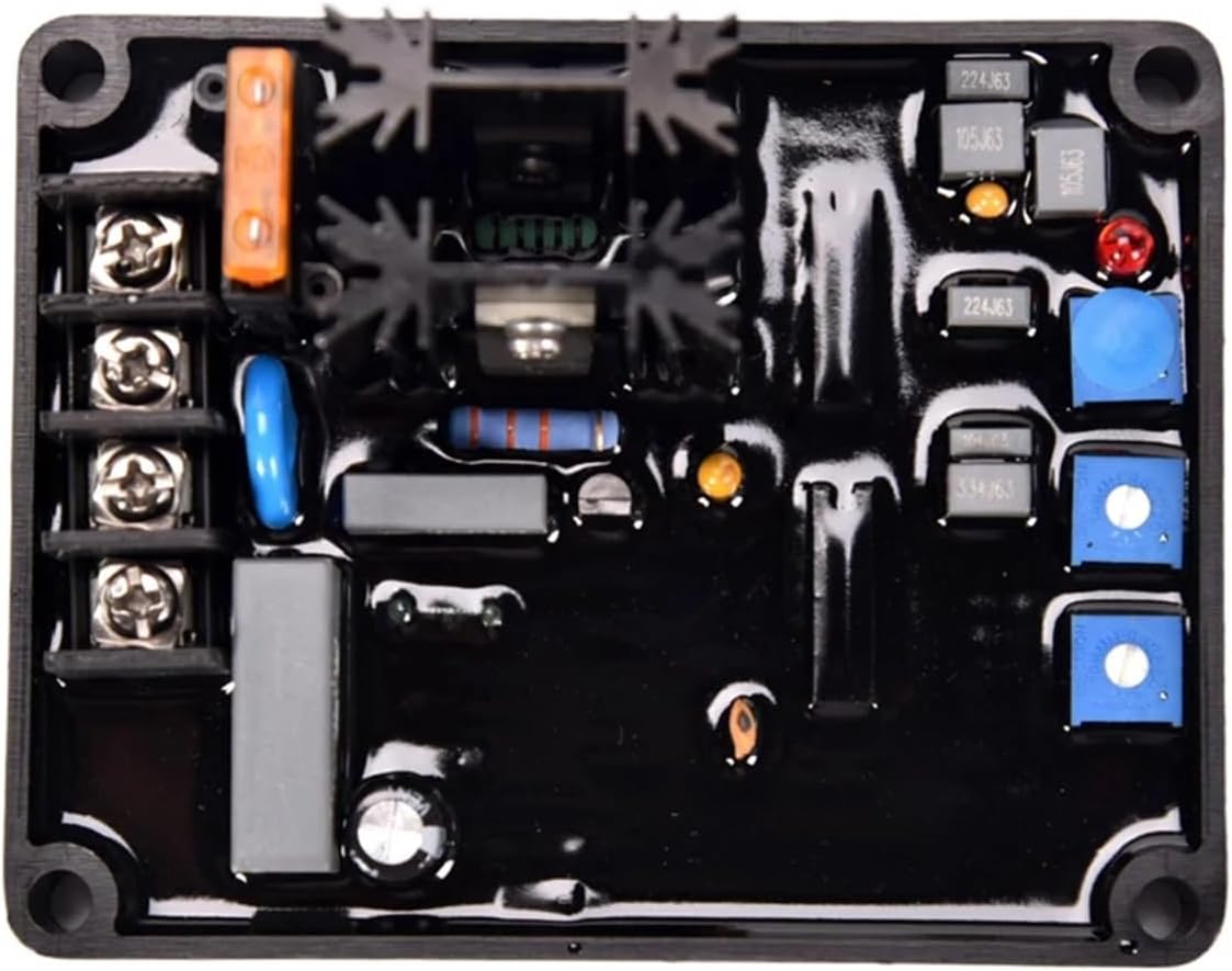
2.2 Components
The CB180 AVR consists of a circuit board housed within a protective casing, featuring various electronic components, terminals for electrical connections, and adjustment potentiometers for fine-tuning.

3. Setup and Installation
3.1 Safety Precautions
- Ensure the generator set is completely shut down and disconnected from all power sources before attempting installation or maintenance.
- Installation should only be performed by qualified and experienced personnel to prevent electrical hazards and equipment damage.
- Verify correct wiring polarity and connections to prevent damage to the AVR and the generator system.
3.2 Installation Steps
- Mount the CB180 AVR securely in a location that is free from excessive vibration, moisture, and extreme temperatures. Ensure adequate ventilation.
- Connect the field winding terminals (F+, F-) from the generator to the corresponding terminals on the AVR.
- Connect the auxiliary power input (X1, X2) from the generator to the AVR. Refer to your specific generator's wiring diagram for precise connection points.
- Double-check all electrical connections for tightness and correct polarity to ensure reliable operation.

4. Operating Instructions
4.1 Initial Start-up
- After completing the installation and verifying all connections, start the generator set according to its manufacturer's instructions.
- Monitor the generator's output voltage. The AVR should automatically regulate the voltage to the specified operational level.
4.2 Adjustments
The CB180 AVR may feature adjustment potentiometers for fine-tuning voltage (VOLT), stability (STAB), and under-frequency protection (U/F). These are typically small, labeled screws on the circuit board.
- VOLT: Adjusts the main output voltage. Turn clockwise to increase voltage, counter-clockwise to decrease.
- STAB: Adjusts the stability of the voltage output. Adjust as needed to prevent voltage fluctuations or oscillations.
- U/F: Sets the under-frequency protection threshold. This feature helps prevent damage to the generator at low engine speeds by reducing excitation.
Caution: Make adjustments incrementally and observe the generator's behavior carefully. Incorrect adjustments can lead to unstable operation, equipment damage, or electrical hazards.
5. Maintenance
5.1 General Maintenance
- Periodically inspect the AVR for any signs of physical damage, loose connections, or corrosion on the terminals.
- Ensure the area around the AVR is clean and free from dust, debris, and moisture to allow for proper heat dissipation and prevent short circuits.
- Do not attempt to open or repair the AVR unit yourself. Refer to qualified service personnel for any repairs or internal inspections.
6. Troubleshooting
6.1 Common Issues and Solutions
| Problem | Possible Cause | Solution |
|---|---|---|
| No Voltage Output | Incorrect wiring; Blown fuse in excitation circuit; AVR malfunction. | Check all connections for correctness and tightness; Inspect and replace any blown fuses if necessary; If problem persists, consult a qualified technician. |
| Unstable Voltage | Incorrect STAB adjustment; Engine speed fluctuations; Loose connections. | Adjust the STAB potentiometer incrementally; Check engine governor and fuel system for stable speed; Verify all electrical connections are secure. |
| Overvoltage/Undervoltage | Incorrect VOLT adjustment; AVR malfunction; Generator overload. | Adjust the VOLT potentiometer to the desired output; Reduce generator load if overloaded; If problem persists, consult a qualified technician. |
7. Specifications
7.1 Technical Data
- Model: CB180
- Brand: AAXTUVCL
- Item Weight: Approximately 1.76 ounces (50 grams)
- Package Dimensions: Approximately 0.39 x 0.39 x 0.39 inches (1 x 1 x 1 cm)
- Manufacturer: AAXTUVCL
- ASIN: B0FK21V2F2
- Date First Available: July 26, 2025
8. Warranty and Support
For warranty information or technical support regarding your AAXTUVCL CB180 Automatic Voltage Regulator, please contact your vendor or the manufacturer, AAXTUVCL. Specific warranty terms and conditions may vary by region and retailer.