1. Introduction
This manual provides detailed instructions for the proper setup, operation, and maintenance of your GLOBACT HOTRC CT-6A 6-channel radio transmitter and F-06A receiver. Please read this manual thoroughly before using the product to ensure safe and efficient operation.
1.1 Package Contents

The product packaging includes the following items:
- 1 × CT-6A 2.4G 6CH Radio Transmitter
- 1 × F-06A Receiver
- 1 × RC Transmitter Lanyard
- 1 × Instruction Book
2. Product Overview
The GLOBACT HOTRC CT-6A is a 6-channel radio transmitter designed for various RC models including crawlers, drift cars, trucks, boats, and tanks. It features 2.4G FHSS technology for strong anti-interference and stable performance.

The image displays the GLOBACT HOTRC CT-6A 6-channel radio transmitter, the F-06A receiver, and a branded lanyard. The transmitter features a pistol-grip design with a steering wheel, a display screen, and various control buttons. The compact receiver has multiple ports for connections.
2.1 Transmitter Components

A detailed diagram of the HOTRC CT-6A transmitter, labeling its various components such as the charging port, internal antenna, directional joystick, single-hand operation steering wheel, throttle trigger, metal pendant, and battery compartments (18650 and AA).
2.2 Control Panel Overview
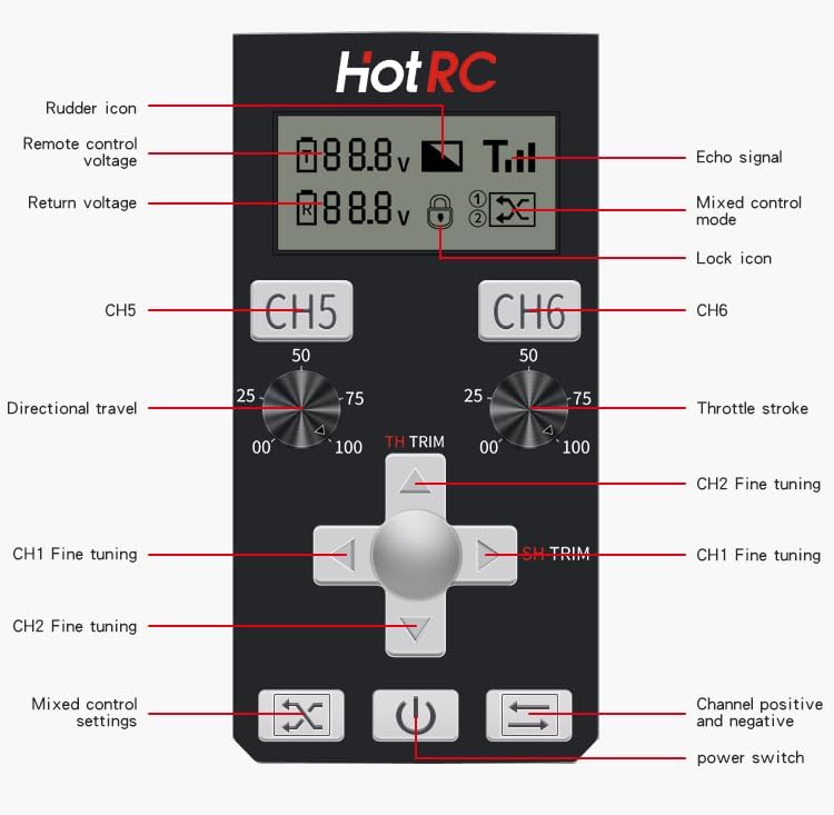
This image provides a detailed breakdown of the CT-6A's control panel. Labels indicate the rudder icon, remote control voltage, return voltage, echo signal, mixed control mode, lock icon, CH5/CH6 controls, directional travel, throttle stroke, CH1/CH2 fine tuning, mixed control settings, and power switch.
2.3 Receiver F-06A
The F-06A is a standard 6-channel receiver that transmits battery voltage and receiver signal. It is equipped with a return signal cable with a plug, and the alarm voltage can be set via the radio transmitter. Digital servo mode can also be set.
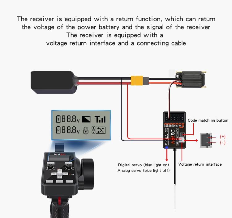
A diagram illustrating the F-06A receiver's connections, including the code matching button, positive and negative terminals, signal ports (PWM 1-6), and the voltage return interface with its connecting cable. It also shows how the receiver transmits battery voltage and signal back to the transmitter.
3. Setup
3.1 Power Supply
The transmitter supports three power supply modes: 18650 battery, 2S lithium battery, or 4 No. 5 (AA) batteries. It can be powered by two types of batteries simultaneously for extended standby. The remote control can also charge 18650 batteries.

This image illustrates the three power supply modes supported by the transmitter: 18650 battery, 2S lithium battery, and 4 No. 5 (AA) batteries. It shows how two types of batteries can power the device simultaneously for extended standby, and notes that the 18650 batteries can also be charged by the remote control. Note: The product does not include the battery part; please purchase it separately.
3.2 Code Matching (Binding)
Code matching is essential to establish communication between the transmitter and receiver. Follow these steps:
- Power up the receiver: Connect the receiver to a power source. The green light on the receiver will enter a slow flashing state.
- Initiate matching on receiver: Press the code matching button on the receiver once. The green light will start flashing rapidly, indicating it's ready for matching.
- Turn on the transmitter: Power on the CT-6A transmitter.
- Verify connection: A constant green light on the receiver indicates successful code matching.
For a visual guide, refer to the video below:
Video Description: This video demonstrates the step-by-step process for code matching the GLOBACT HOTRC CT-6A transmitter with the F-06A receiver. It also explains how to set up and utilize the loss of control protection function, which helps prevent damage by setting a default throttle value if the signal is lost.
4. Operating Instructions
4.1 Basic Operation
The CT-6A transmitter features a two-color sponge handwheel for comfortable and precise control, allowing for single-handed operation. The integrated screen provides visual feedback on transmitter voltage, return voltage, and signal strength.

A close-up view of the HOTRC CT-6A transmitter's color screen, illustrating real-time display of transmitter voltage, return voltage, return signal strength, and mixed control status. This screen provides essential operational data at a glance.
4.2 Advanced Functions
The transmitter includes several advanced features to enhance control and safety:
- Hybrid Control: Allows for combined control of multiple channels.
- Anti-Misoperation Lock: Prevents accidental changes to settings. Remote control CH1 & CH2 can be mixed, and CH5 & CH6 can be mixed.
- Channel Forward and Reverse: CH1 & CH2 can be set with both positive and negative positions.
- Loss of Control Protection (Runaway Protection): This protective function activates when the receiver loses its signal, causing the throttle channel to run to a pre-set value. This helps prevent damage by maintaining a safe state.

This image highlights several key features of the HOTRC CT-6A. It shows the dual-color sponge wheel designed for single-handed operation, the lock function for preventing accidental control changes, hybrid control capabilities, a metal pendant button, and channel positive/negative loss of control protection.
4.3 Setting Up Runaway Protection
To set up the runaway protection function:
- Turn off the remote control.
- Press and hold the Lower Fine Adjustment button (indicated by a down arrow) without releasing it.
- While holding the button, simultaneously turn on the power switch of the remote control. The remote control light will flash quickly with sound, and the receiver's blue and green lights will flash simultaneously, indicating entry into the setting state.
- At this point, adjust the throttle channel to the desired runaway protection value.
- Press the Lower Fine Adjustment button again to save the data and exit the setting mode.
Refer to the video in Section 3.2 for a demonstration of this feature.
5. Maintenance
To ensure the longevity and optimal performance of your GLOBACT HOTRC CT-6A system, follow these maintenance guidelines:
- Keep the transmitter and receiver clean and free from dust, dirt, and moisture.
- Store the unit in a dry, cool place away from direct sunlight and extreme temperatures.
- Regularly check battery compartments for corrosion and ensure proper battery installation.
- Avoid dropping or subjecting the unit to strong impacts.
- Do not attempt to disassemble or modify the internal components, as this may void the warranty and cause damage.
6. Troubleshooting
If you encounter issues with your GLOBACT HOTRC CT-6A system, refer to the following common problems and solutions:
- No power: Ensure batteries are correctly installed and fully charged. Check for any loose connections.
- Loss of signal/connection: Verify that the transmitter and receiver are properly code-matched (bound) as described in Section 3.2. Ensure there are no major obstructions or sources of interference between the transmitter and receiver. Check the range of operation.
- Controls unresponsive or erratic: Re-check code matching. Ensure all servo connections to the receiver are secure. Verify that the batteries in both the transmitter and the RC model are adequately charged.
- Trim functions not working: Ensure the transmitter is not in a locked mode that prevents trim adjustments. Refer to the control panel overview in Section 2.2 for trim button locations.
If problems persist after attempting these solutions, please contact customer support.
7. Specifications
Below are the technical specifications for the GLOBACT HOTRC CT-6A system:

A table detailing the production information and technical specifications of the GLOBACT HOTRC CT-6A. This includes suitable types (Model car/ship/tank), spread spectrum (FHSS), number of channels (6), response speed (PWM: <=20ms), net weight (230g), frequency range (2.4GHz ISM), remote control distance (approx. 300m ground, 800m air), receiver sensitivity (-96dbm), transmit power (~90mA), receiver power supply (DC 4V-9V), modulation mode (GFSK), and transmitter power supply (DC 4V-9V).
| Feature | Specification |
|---|---|
| Product Dimensions | 7.09 x 4.13 x 9.65 inches |
| Item Weight | 15.7 ounces |
| Manufacturer Recommended Age | 14 years and up |
| Manufacturer | GLOBACT |
8. Warranty and Support
8.1 Warranty Information
Specific warranty details for the GLOBACT HOTRC CT-6A are not provided in this manual. Please refer to the product packaging or contact GLOBACT customer service for warranty terms and conditions.
8.2 Customer Support
For technical assistance, troubleshooting, or any inquiries regarding your GLOBACT HOTRC CT-6A system, please contact GLOBACT customer support through their official website or the retailer where the product was purchased.