1. Introduction
This manual provides detailed instructions for the setup, operation, and maintenance of your GLOBACT HOTRC CT-8A 2.4G 8CH Radio Transmitter and Receiver. This system is designed for various RC models including 1/8, 1/10, 1/18, and 1/24 scale RC crawlers, drift cars, trucks, boats, and tanks.
The CT-8A utilizes 2.4G FHSS (Frequency Hopping Spread Spectrum) technology for strong anti-interference capabilities and stable performance. It features an 8-channel control system and a metal handwheel for enhanced durability and precise control.

Image 1.1: The GLOBACT HOTRC CT-8A 2.4G 8CH Radio Transmitter and its accompanying F-08A Receiver.
2. Product Features
- 2.4G FHSS Technology: Ensures strong anti-interference and stable control over distances up to 300 meters on ground and 800 meters in air.
- 8-Channel Control: Supports various RC models with multiple functions.
- Metal Handwheel: Replaces traditional sponge handwheels for improved durability and control feel.
- Multifunctionality: Includes anti-misoperation lock, cruise control, automatic shutdown after 15 minutes of standby, and trainer function.
- Rechargeable Battery Support: Compatible with 18650 lithium batteries, 2S lithium batteries, and AA batteries. Features a Type-C charging port.
- F-08A Receiver: Standard 8-channel receiver with battery voltage and signal return function. Alarm voltage can be set via the transmitter.
- Adjustable Controls: Trigger spring force, trigger opening size, and rocker assembly with 4 ball bearings for precise adjustments.
- Color Screen Display: 2.4-inch color screen for clear display of parameters and settings.

Image 2.1: Detailed view of the CT-8A transmitter's key features, highlighting the metal handwheel, electroplated buttons, and Type-C charging port.
3. Package Contents
Please verify that all items are present in your package:
- 1 x CT-8A Radio Transmitter
- 1 x F-08A Receiver
- 1 x RC Transmitter Lanyard
- 1 x Voltage Return Line
- 1 x Data Cable
- 1 x Instruction Manual (this document)

Image 3.1: Visual representation of the items included in the standard CT-8A package.
4. Setup
4.1. Battery Installation
The CT-8A transmitter supports three power supply methods:
- 18650 Lithium Battery: Insert an 18650 battery into the designated compartment within the grip.
- 2S Lithium Battery: Connect a 2S LiPo pack using the balance connector in the 2S lithium battery compartment.
- AA Batteries: Use the provided tray to install four AA batteries into the 5th battery compartment.
The remote control can simultaneously supply power from two types of batteries, extending standby usage time. The 18650 battery can also be charged directly via the transmitter's Type-C port.

Image 4.1: The CT-8A transmitter's battery compartments, showing options for 18650, 2S LiPo, and AA batteries. Batteries are not included.
4.2. Receiver Connection
Connect the F-08A receiver to your RC model's electronic speed controller (ESC) and servos. Ensure correct polarity for all connections. The receiver supports a voltage return function, allowing you to monitor battery voltage and signal strength via the transmitter.

Image 4.2: Connection diagram for the F-08A receiver, including the return line for voltage feedback.
4.3. Binding (Pairing) the Transmitter and Receiver
To establish communication between the transmitter and receiver:
- Ensure both the transmitter and receiver are powered off.
- Connect the receiver to power (e.g., via the ESC).
- Press and hold the 'Code matching button' on the F-08A receiver.
- While holding the button, power on the receiver. The receiver's LED should flash, indicating it is in binding mode.
- Power on the CT-8A transmitter.
- The receiver's LED should turn solid, indicating successful binding.
- Test the controls to ensure proper function.
4.4. Attaching the Lanyard
Attach the provided lanyard to the metal pendant on the transmitter for secure handling during operation.
5. Operating Instructions
5.1. Transmitter Layout and Controls

Image 5.1: Labeled components of the CT-8A transmitter, including the antenna, directional joystick, throttle trigger, channel buttons, and battery compartments.
- Antenna: For signal transmission.
- Directional Joystick (Steering Wheel): Controls steering. Features a metal handwheel for durability.
- Throttle Trigger: Controls acceleration and braking/reverse.
- Operation Panel Channel Buttons (A, B, C, D): Assignable auxiliary channels.
- SWA/SWB Channels: Switch channels for additional functions.
- Power Button: Long press to turn on/off.
- Scroll Wheel Button: Scroll up/down for function selection. Short press to confirm/enter. Long press to pause/clear timing.
- Charging Port (Type-C): For charging compatible batteries and firmware upgrades.
- Training Port: For trainer function.
5.2. Screen Interface and Settings
The 2.4-inch color screen displays various parameters and allows for detailed adjustments. The interface can be switched between Chinese and English.

Image 5.2: The CT-8A screen displaying real-time data such as receiver voltage (RX V), signal strength (RSSI), transmitter voltage (TX V), channel values, timer, and gyroscope settings.
Key indicators and settings include:
- RX V / TX V: Receiver and Transmitter voltage.
- RSSI: Receiver Signal Strength Indicator.
- CH 1-8: Channel output values.
- Timer: Elapsed time.
- Gyroscope: Gyro settings (P, I, A).
- Direction Travel (ST L/R): Steering travel adjustment.
- Throttle Travel (TH F/B): Throttle forward/backward travel adjustment.
5.3. Special Functions
- Anti-Misoperation Lock: Prevents accidental input. Refer to the on-screen menu for activation/deactivation.
- Cruise Control: Supports cruise control for the throttle channel. Activate via the menu.
- Automatic Shutdown: The transmitter will automatically shut down after 15 minutes of inactivity to conserve battery.
- Trainer Function: Allows for connection to another transmitter for training purposes. Use the dedicated training port.
- Voltage Alarm: Set a low voltage alarm threshold for the receiver battery via the transmitter menu.
5.4. Adjusting Controls
The CT-8A offers adjustable physical controls for a personalized feel:
- Throttle Trigger: Adjust the trigger spring force and the trigger opening size to suit your preference. The textured trigger surface helps prevent slipping.
- Rocker Assembly: The newly designed rocker assembly features 4 ball bearings for smooth and precise steering input.
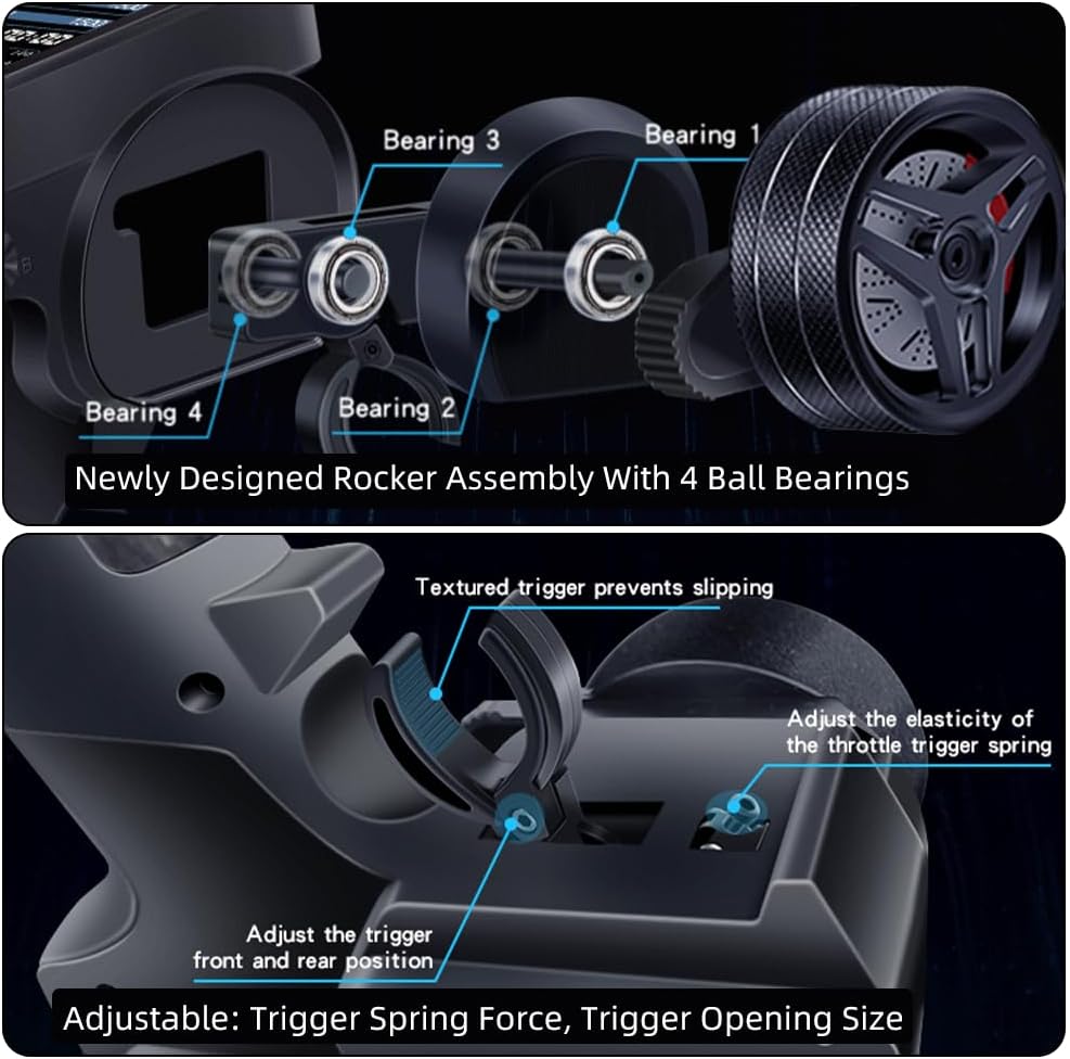
Image 5.3: Illustrations of the adjustable throttle trigger mechanism and the 4-ball bearing rocker assembly for enhanced control.
6. Maintenance
- Cleaning: Use a soft, dry cloth to clean the transmitter and receiver. Avoid using solvents or abrasive cleaners.
- Storage: Store the unit in a cool, dry place away from direct sunlight and extreme temperatures. Remove batteries if storing for extended periods.
- Battery Care: Always use appropriate chargers for your chosen battery type (18650, 2S LiPo, or AA). Do not overcharge or deep discharge lithium batteries.
- Firmware Updates: Check the GLOBACT official website for any available firmware updates for your CT-8A transmitter. Updates can typically be performed via the Type-C port.
7. Troubleshooting
- No Power: Ensure batteries are correctly installed and charged. Check battery compartment contacts for corrosion.
- No Signal/Loss of Control: Re-bind the transmitter and receiver (refer to Section 4.3). Ensure the receiver antenna is not obstructed or damaged. Check the distance between the transmitter and receiver.
- Controls Not Responding Correctly: Verify servo connections to the receiver. Check for proper calibration in the transmitter's settings menu. Ensure no physical obstructions are affecting the steering wheel or throttle trigger.
- Screen Not Displaying: Check battery level. If the screen remains blank, contact customer support.
- Short Range: Ensure the transmitter antenna is fully extended and not damaged. Avoid operating in areas with high electromagnetic interference.
8. Specifications
| Feature | Specification |
|---|---|
| Brand | GLOBACT |
| Model Name | CT-8A 8CH Radio Transmitter & Receiver |
| Number of Channels | 8 |
| Spread Spectrum | FHSS |
| Frequency Range | 2.4GHz ISM |
| Modulation Mode | GFSK |
| Remote Control Distance | Approx. 300m (ground), 800m (air) |
| Transmit Power | ≈160mA-300mA |
| Receiver Sensitivity | -96 dbm |
| Receiver Power Supply | DC 3.5V-9V |
| Transmitter Power Supply | DC 3.7V-9V (Rechargeable, 18650, 2S LiPo, AA) |
| Response Speed | PWM: ≤20ms |
| Net Weight | 230g |
Note: Remote control distance is for reference only, and actual use may vary depending on different environments.