1. Introduction
This manual provides detailed instructions for the installation, operation, and maintenance of the DBEIXIWEI ZK-TB21F 2.1CH Bluetooth 5.0 Audio Power Amplifier Board Module. This module is designed to deliver superior audio quality with versatile expansion capabilities for subwoofers and microphone preamps.
2. Safety Information
WARNING:
- Do not mix old and new batteries.
- Do not mix alkaline, standard (carbon-zinc), or rechargeable batteries.
The ZK-TB21F amplifier board is equipped with multiple protection mechanisms to ensure safe operation. These include overvoltage, undervoltage, overheating, branched current detection, and short circuit protection.

Image: EC REP and battery warning label, indicating general safety precautions for electronic devices.
3. Product Overview
The ZK-TB21F is a 2.1 channel Bluetooth 5.0 audio power amplifier board module featuring a high-quality TPA3116D2 amplifier chip with AM interference suppression. Its design allows for flexible potentiometer separation, enhancing user convenience. The module supports subwoofer expansion and the addition of a microphone preamp board for diverse audio experiences.
Key Features:
- Elegant design with a well-arranged component layout.
- Comprehensive safety features: overvoltage, undervoltage, overheating, DC detection, and short-circuit protection.
- Flexible potentiometer separation for easy integration.
- High-quality TPA3116D2 amplifier chip with AM interference suppression.
- Supports subwoofer expansion and microphone preamp board integration.
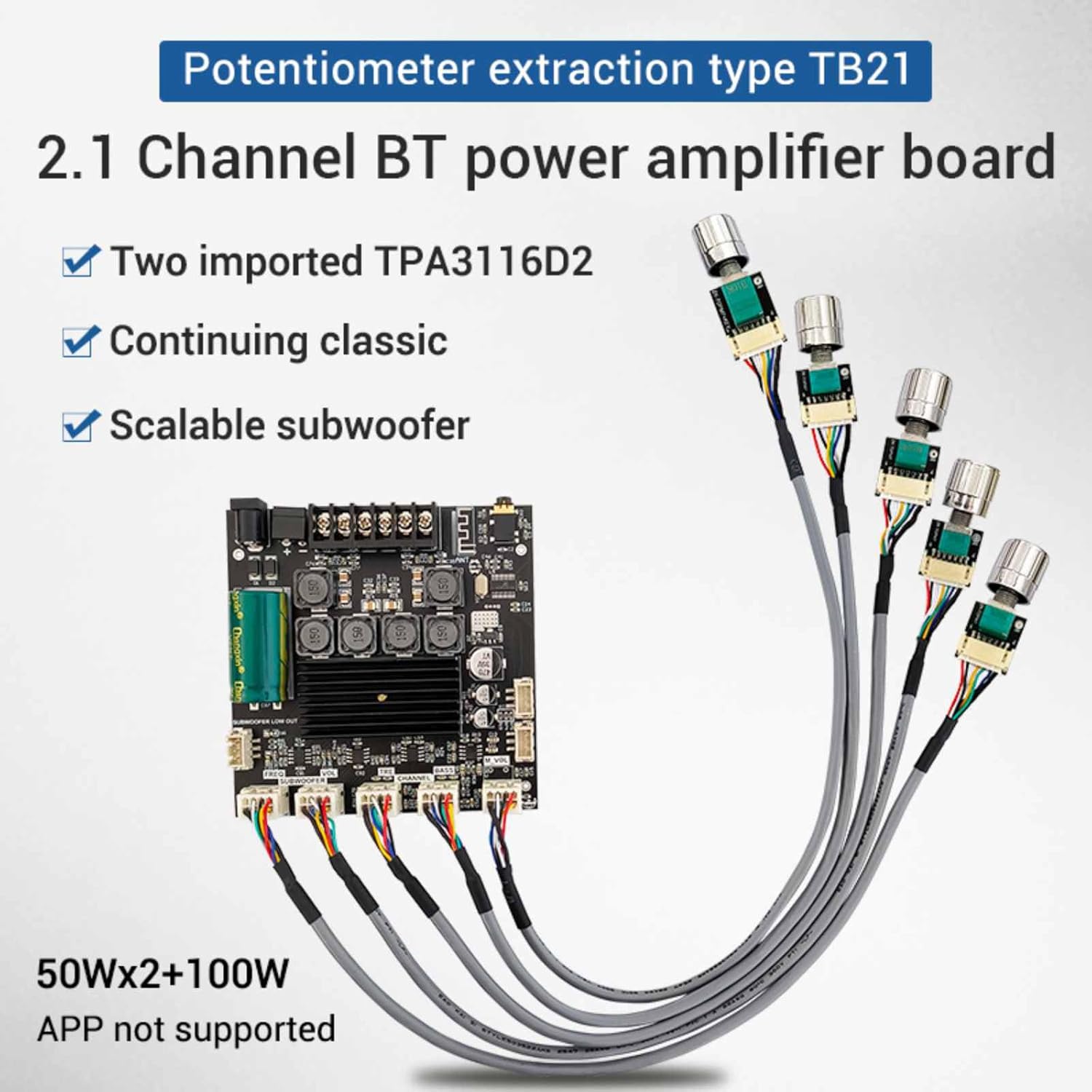
Image: The ZK-TB21F 2.1 Channel BT power amplifier board, showcasing two TPA3116D2 chips, scalable subwoofer support, and external potentiometers for control. Output power is 50W x 2 + 100W for subwoofer.
4. Specifications
| Specification | Detail |
|---|---|
| Product Model | ZK-TB21F |
| Bluetooth Version | 5.0 (Unobstructed range: 10 meters) |
| Input Sensitivity | 500mV |
| Input Mode | AUX + Bluetooth |
| Number of Channels | 2.1 channels |
| Power Amplifier Chip | TPA3116D2 (with AM interference suppression) |
| Power Supply | DC 12V ~ 24V / 5A or more |
| Applicable Speakers | 20W ~ 100W, 4Ω ~ 8Ω |
| Output Power | Left/Right Channels ≤ 50W, Subwoofer ≤ 100W |
| Protection Mechanisms | Over-voltage, Under-voltage, Overheating, DC Detection, Short-circuit Protection |
| Dimensions (L x W x H) | 100mm x 100mm x 18mm (approx. 3.94 x 3.94 x 0.7 inches) |
| Item Weight | 7.2 ounces |

Image: Diagram showing the physical dimensions of the ZK-TB21F amplifier board, measuring approximately 10cm x 10cm x 1.8cm.
5. Setup and Installation
5.1. Subwoofer Expansion
To expand the subwoofer functionality, connect the subwoofer small signal output from the ZK-TB21F board to the input port of a pure rear power amplifier board. Ensure the power supply for the subwoofer speaker is within 15-35VDC and the main board power supply is 12-24VDC.
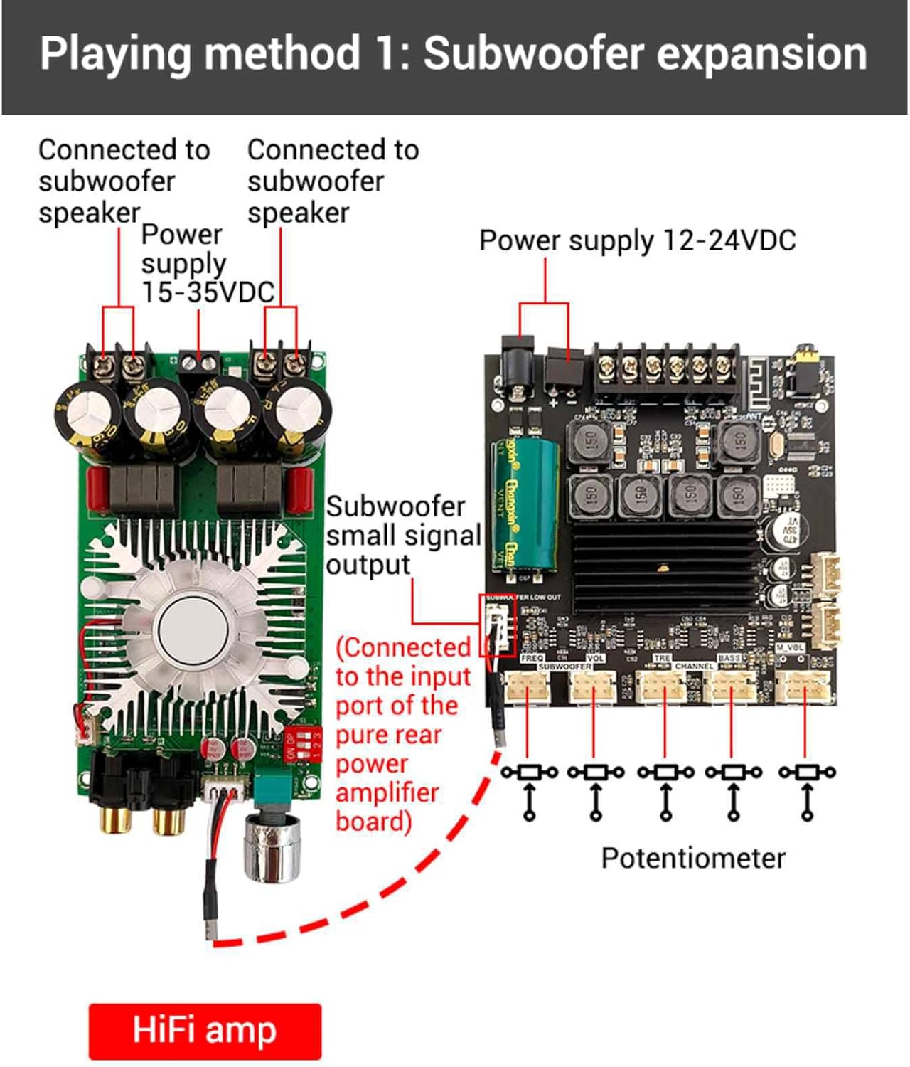
Image: Wiring diagram illustrating how to connect the ZK-TB21F amplifier board for subwoofer expansion, showing connections to a subwoofer speaker and an external HiFi amplifier.
5.2. Potentiometer Connections
The ZK-TB21F board utilizes an extraction-type potentiometer design, allowing for flexible placement. Connect the provided potentiometers to their respective ports on the amplifier board for volume, bass, and treble control.
5.3. Modifying for Qualcomm Bluetooth (Optional)
For advanced users wishing to modify the board for Qualcomm Bluetooth, connect an external Qualcomm decoding board. When using expansion port 1 and expansion port 2 for this modification, it is necessary to remove the three 0 ohm resistors (R75, R74, and R19) from the main board. The Qualcomm decoding board typically requires a power supply of 8-32VDC.
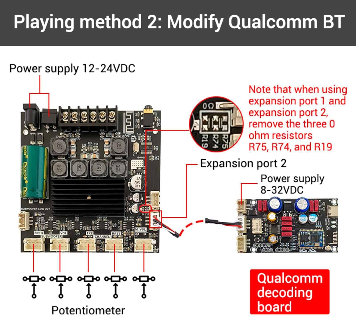
Image: Wiring diagram for modifying the ZK-TB21F board to integrate a Qualcomm decoding board, highlighting the removal of specific resistors (R75, R74, R19) and power supply connections.
5.4. Retrofitting a Microphone Preamp Board (Optional)
To add microphone functionality, retrofit a microphone front stage board. Connect expansion port 1 to the microphone front stage board's reverb input and expansion port 2 to its reverb output. The microphone front stage board typically requires a power supply of 8-26VDC. Remember to remove the three 0 ohm resistors (R75, R74, and R19) when utilizing expansion ports 1 and 2.
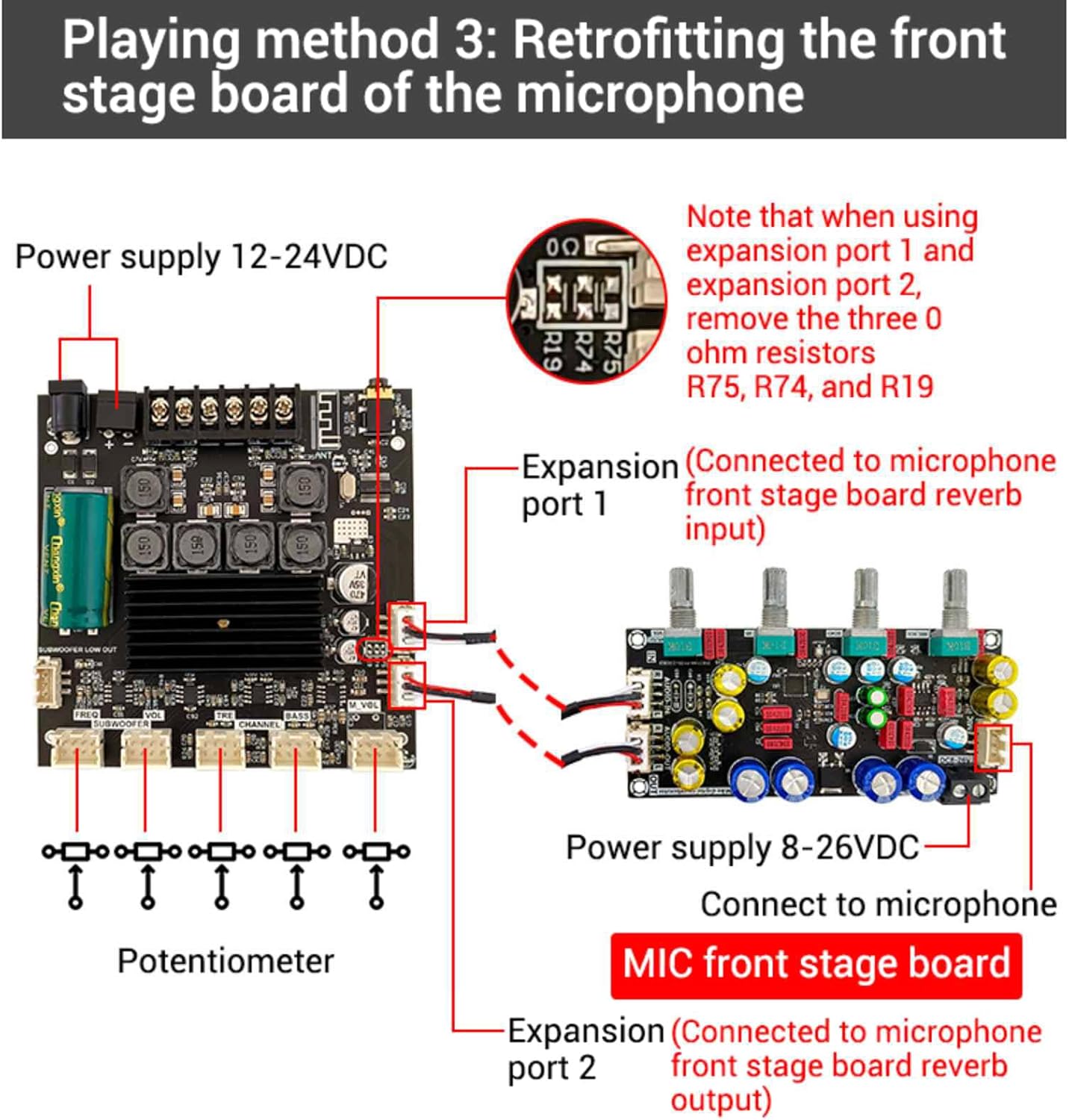
Image: Wiring diagram for retrofitting a microphone front stage board to the ZK-TB21F, showing connections to expansion ports and power supply, along with the note about resistor removal.
5.5. Wiring Considerations
Utilize high-density wrapped shielded wires with high-quality connectors for optimal signal integrity. The outer winding shield, made of tinned copper wire, provides effective shielding for connecting signals, reducing noise and interference.

Image: Example of high-density wrapped shielded wires with high-quality connectors, emphasizing their role in signal shielding and noise reduction.
6. Operation
Once the amplifier board is correctly installed and powered, you can operate it via AUX input or Bluetooth 5.0. Use the connected potentiometers to adjust the main volume, bass, and treble levels. Ensure your audio source is properly connected and the power supply meets the specified requirements for optimal performance.
7. Maintenance
The ZK-TB21F amplifier board requires minimal maintenance. Keep the board clean and free from dust. Avoid exposing it to moisture or extreme temperatures. Periodically check all connections to ensure they are secure. Do not attempt to repair the board yourself if you are not qualified; contact a professional.
8. Troubleshooting
- No Sound Output: Verify all power connections and audio input sources. Ensure speakers are correctly wired and functional. Check that the volume potentiometers are not set to minimum.
- Low Output Power: To maximize output power, ensure that both the audio input signal and the power supply voltage/current are sufficient. A higher power supply voltage and lower speaker impedance will generally increase output power. Always ensure the adapter power supply's rating exceeds the amplifier's actual working power requirements.
- Distorted Audio: Check for proper grounding. Ensure input signal levels are not too high, causing clipping. Verify speaker impedance matches the amplifier's specifications.
- Bluetooth Connection Issues: Ensure the amplifier board is within the 10-meter unobstructed range of the Bluetooth device. Disconnect and reconnect the Bluetooth device.
- Protection Mechanism Activated: If the board shuts down unexpectedly, one of the protection mechanisms (over-voltage, under-voltage, overheating, DC detection, short-circuit) may have been triggered. Disconnect power, inspect for any faults (e.g., short circuits in wiring), and allow the board to cool down before reconnecting.
9. Warranty and Support
Warranty information for the DBEIXIWEI ZK-TB21F 2.1CH Bluetooth 5.0 Audio Power Amplifier Board Module is not provided within this manual. Please refer to your purchase documentation or contact the retailer for details regarding warranty coverage and technical support.