1. Introduction
This manual provides comprehensive instructions for the installation, operation, and maintenance of your Miuputake V701 Non-Programmable Thermostat. This thermostat is designed for conventional single-stage heating and cooling systems (1 Heat/1 Cool) to effectively control indoor temperatures. Please read this manual thoroughly before installation and use to ensure proper function and safety.

Image 1: Miuputake V701 Non-Programmable Thermostat. This image displays the front view of the thermostat, highlighting its large, backlit LCD screen with temperature readings and mode indicators.
2. Safety Information
Always turn off power to the heating/cooling system at the main fuse or circuit breaker panel before installing or servicing the thermostat. Failure to do so could result in electrical shock or equipment damage. If you are unsure about any part of the installation process, it is recommended to consult a qualified HVAC technician.
Ensure all wiring connections are secure and comply with local electrical codes. This thermostat is designed for 24VAC systems. Do not use with line voltage systems (110-240 Volts).
3. Package Contents
Verify that all items are present in your package:
- Miuputake V701 Thermostat
- Two Screws and Anchors
- Operating Manual (this document)
- Cable Labels

Image 2: Package Contents. This graphic shows the Miuputake V701 thermostat, its instruction manual, wiring labels, and mounting hardware (screws and anchors).
4. Product Features and Overview
The Miuputake V701 is a non-programmable thermostat designed for ease of use and reliable temperature control. Key features include:
- Non-programmable operation for conventional single-stage systems (1 Heat/1 Cool).
- Large, clear, and easy-to-read backlit LCD display.
- Separate heating and cooling swing (cycle rate) adjustment for comfort and energy efficiency.
- Dual power supply: operates on 24VAC power or 2 AAA batteries.
- No common wire (C-wire) required on most systems (only required on heat-only and cool-only systems).
- Setpoint limit option for defining maximum heat and minimum cool settings.

Image 3: Product Features. This graphic illustrates the main features of the Miuputake V701 thermostat, including its display, control options, and power flexibility.
5. Installation
5.1 Pre-Installation Checklist
- Ensure your system is a conventional single-stage (1 Heat/1 Cool) system.
- Turn off power to your HVAC system at the circuit breaker.
- Remove your old thermostat. Take a picture of the wiring connections for reference.
- Label each wire with the provided cable labels according to the terminal it was connected to on your old thermostat.
5.2 Mounting the Thermostat Base
The Miuputake V701 thermostat features a universal sub-base for easy installation. The base can be attached to the wall using the provided screws and anchors.
- Separate the thermostat face from its base.
- Position the base on the wall where you want to install the thermostat.
- Mark the screw holes.
- Drill pilot holes if necessary and insert wall anchors.
- Secure the thermostat base to the wall using the screws.
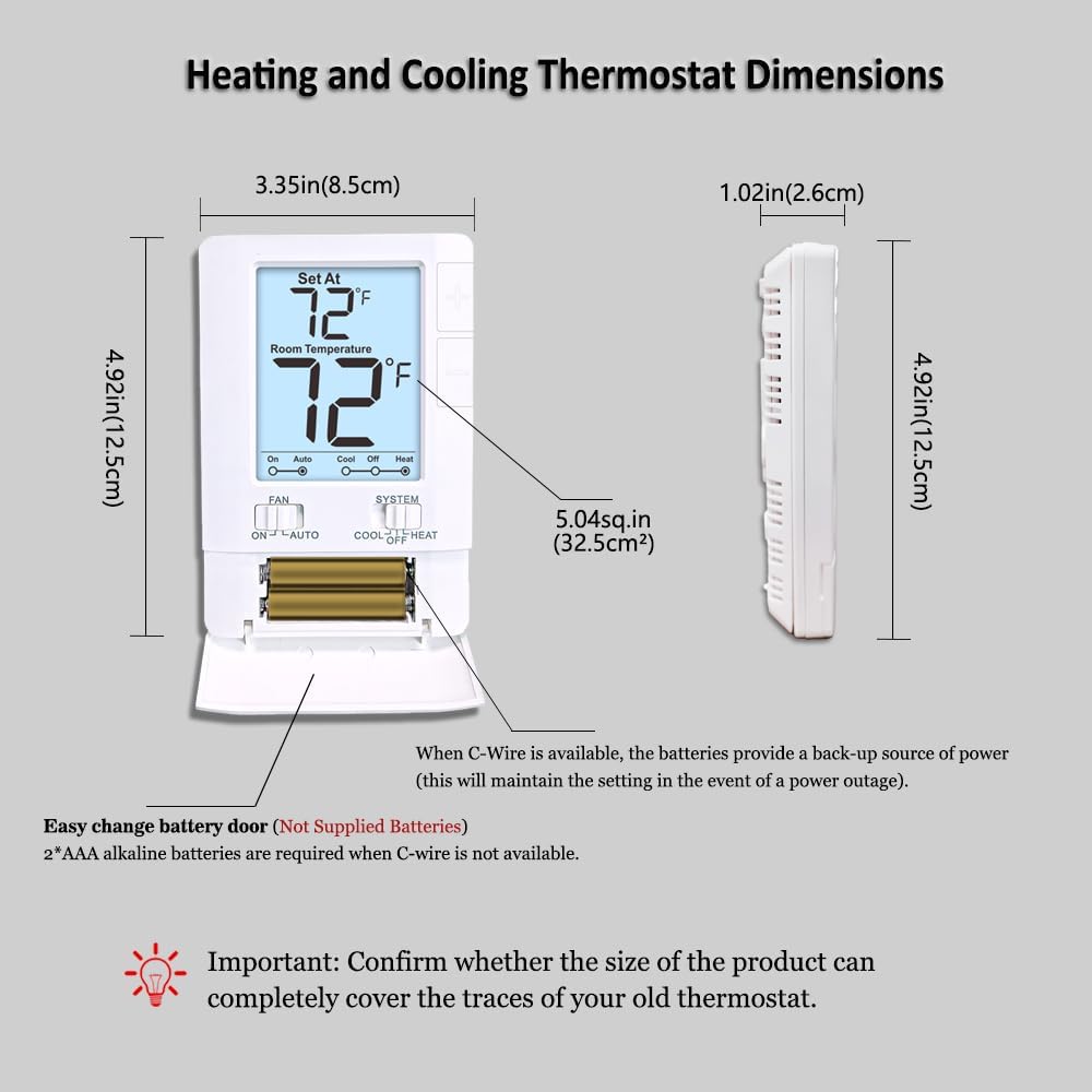
Image 4: Thermostat Back Panel. This image shows the rear of the thermostat, detailing the terminal block for wiring connections and the Electric/Gas switch.
5.3 Wiring Connections
Connect the labeled wires from your wall to the corresponding terminals on the thermostat's sub-base. Refer to the diagram below for terminal designations. Ensure wires are securely fastened.
Caution: 4 wires must be connected for use. If only 2 wires are used, batteries must be installed. The base can only be attached with a maximum of 2 to 5 wires. Connections with 6 to 8 wires are not suitable.
| Terminal | Function |
|---|---|
| C | Common 24VAC (system power supply) |
| O | Reversing Valve Cool |
| B | Reversing Valve Heat |
| W | Heat |
| RH | 24VAC (system power supply) - Heat = RH to W |
| RC | Cool = RC to Y, Fan = RC to G |
| G | Fan |
| Y | Cool |
If you have both RH and RC wires, remove the metal jumper wire between RH and RC terminals. If you only have one R wire, connect it to the RH terminal and leave the jumper in place.

Image 5: Thermostat Wiring Terminals. This diagram provides a clear visual guide for connecting system wires to the appropriate terminals on the thermostat's backplate.
5.4 Power Supply
The thermostat can be powered by 24VAC from your HVAC system or by two AAA batteries. If your system does not provide a C-wire, batteries are required. When a C-wire is available, batteries provide a backup power source in case of a power outage.
To install batteries: Open the battery compartment on the front of the thermostat and insert 2 AAA alkaline batteries, observing polarity. Close the compartment.
Video 1: Miuputake V701 Thermostat Overview. This video demonstrates the physical aspects of the thermostat, including its battery compartment and the separation of the front panel from the backplate for installation.
After wiring and battery installation (if applicable), carefully attach the thermostat face to its base.
Important: Confirm whether the size of the product can completely cover the traces of your old thermostat.
6. Operation
The Miuputake V701 thermostat features a simple, user-friendly interface for manual temperature control.

Image 6: Thermostat Layout. This image labels the various components of the thermostat, including the LCD display, temperature adjustment buttons, and the FAN and SYSTEM switches.
6.1 Setting Temperature
Use the large adjustable up (+) and down (-) buttons on the right side of the thermostat to set your desired temperature. The "Set At" temperature will be displayed at the top of the screen, and the current "Room Temperature" below it.
6.2 Fan Operation
The FAN switch has two settings:
- ON: The fan runs continuously, regardless of whether the heating or cooling system is active.
- AUTO: The fan runs only when the heating or cooling system is actively operating.
6.3 System Mode
The SYSTEM switch has three settings:
- COOL: The thermostat will activate your cooling system when the room temperature rises above your set temperature.
- OFF: The heating and cooling systems are turned off.
- HEAT: The thermostat will activate your heating system when the room temperature falls below your set temperature.
The display will show a flame icon for heating and a snowflake icon for cooling when the respective system is active.
7. System Compatibility
The Miuputake V701 thermostat is compatible with 1 Heat, 1 Cool single-stage systems. Please review the compatibility chart below to ensure your HVAC system is supported.

Image 7: System Compatibility. This chart details which heating and cooling systems are compatible with the Miuputake V701 thermostat, and which are not.
Compatible Systems:
- Gas / Oil / Electric Furnace - Heating Only
- Gas / Oil / Electric Furnace - Single Stage
- Heat Pump without Auxiliary or Emergency Heat
- Floor or Wall Furnaces
- Gas Fireplaces (24V)
- Millivolt Systems
- Forced Air Systems
- Cooling Only Systems
- Single Stage Cooling Systems
Not Compatible With:
- Heat Pump with Auxiliary or Emergency Heat
- Gas / Oil / Electric Furnace - Multi Stage
- Electric Baseboard Heat (110-240 Volts)
- Portable Space Heaters
- Radiant Ceiling Heat
- Convectors
- Mini Split Systems
8. Maintenance
8.1 Battery Replacement
When the 2 AAA batteries are low, a low battery indicator will appear on the display. Replace both batteries promptly to ensure continuous operation, especially if a C-wire is not used. Refer to Section 5.4 for battery installation instructions.
8.2 Cleaning
Clean the thermostat's exterior with a soft, damp cloth. Do not use abrasive cleaners or solvents. Avoid spraying liquids directly onto the thermostat.
9. Troubleshooting
| Problem | Possible Cause | Solution |
|---|---|---|
| No display or blank screen | No power (circuit breaker off, dead batteries, C-wire issue) | Check circuit breaker. Replace batteries. Verify C-wire connection if applicable. |
| Heating/Cooling system not responding | Incorrect wiring, system switch in OFF, set temperature not reached, power off | Verify wiring connections. Ensure SYSTEM switch is set to HEAT or COOL. Adjust set temperature. Check circuit breaker. |
| Inaccurate temperature reading | Thermostat location, calibration issue | Ensure thermostat is not in direct sunlight or near heat sources. Consult advanced settings for calibration if available (refer to full manual if provided). |
| Fan runs continuously in AUTO mode | Fan switch set to ON | Move FAN switch to AUTO. |
10. Specifications
- Brand: Miuputake
- Model Name: V701
- Product Dimensions: 1.02"D x 3.35"W x 4.92"H (2.6cm D x 8.5cm W x 12.5cm H)
- Controller Type: Push Button
- Special Feature: Low Battery Indicator, Setpoint Limit Option
- Color: White
- Specific Uses For Product: Heating and Cooling Controls
- Temperature Control Type: Conventional Single Stage Systems
- Voltage: 24 Volts (AC)
- Material: Plastic
- Display Type: LCD
- Control Method: Touch (buttons)
- Mounting Type: Wall Mount
- Batteries: 2 AAA batteries required (not included)
- Item Weight: 7 ounces

Image 8: Thermostat Dimensions. This image provides a visual representation of the thermostat's height, width, and depth in both inches and centimeters.
11. Warranty and Support
For warranty information or technical support, please refer to the contact details provided with your product packaging or visit the official Miuputake website. Keep your purchase receipt as proof of purchase.