1. Introduction
Thank you for choosing the ZKTOOL LED Power Circuit Probe. This device is designed for comprehensive testing of automotive electrical systems, providing a safe and efficient way to diagnose various electrical issues in vehicles operating on DC 6-24V systems. This manual will guide you through the proper use and care of your new tool.
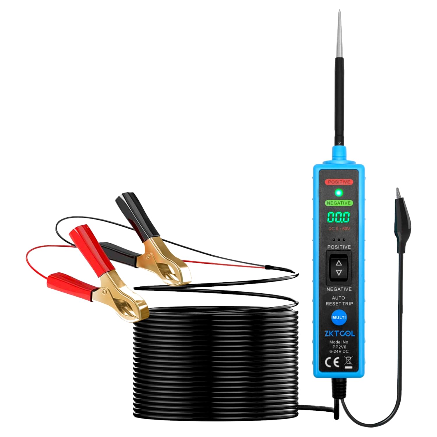
Image 1.1: ZKTOOL LED Power Circuit Probe with its main components, including the probe, digital display, and crocodile clips.
2. Safety Information
Please read and understand all safety warnings and instructions before using this device. Failure to do so may result in electric shock, fire, or serious injury.
- Explosive Environments: Do not use this device near explosive gases, vapors, or dust. Sparks generated by the probe could ignite flammable materials.
- Spark Hazard: When pressing the switch or shaking the device, battery current is directed to the probe tip. This can cause sparks upon contact with ground or certain circuits. Exercise caution to prevent accidental short circuits or ignition of flammable materials.
- Voltage Compatibility: This device is designed exclusively for DC 6-24V vehicle electrical systems. DO NOT use it with 110V or 220V AC household electrical systems or any other voltage outside the specified range.
- Personal Protective Equipment: Always wear appropriate personal protective equipment, such as safety glasses, when working on vehicle electrical systems.
- Insulation: Ensure all connections are properly insulated to prevent accidental contact and short circuits.
3. Product Overview and Features
The ZKTOOL LED Power Circuit Probe is an advanced tool for automotive electrical diagnostics. It offers enhanced safety and functionality compared to traditional testers.
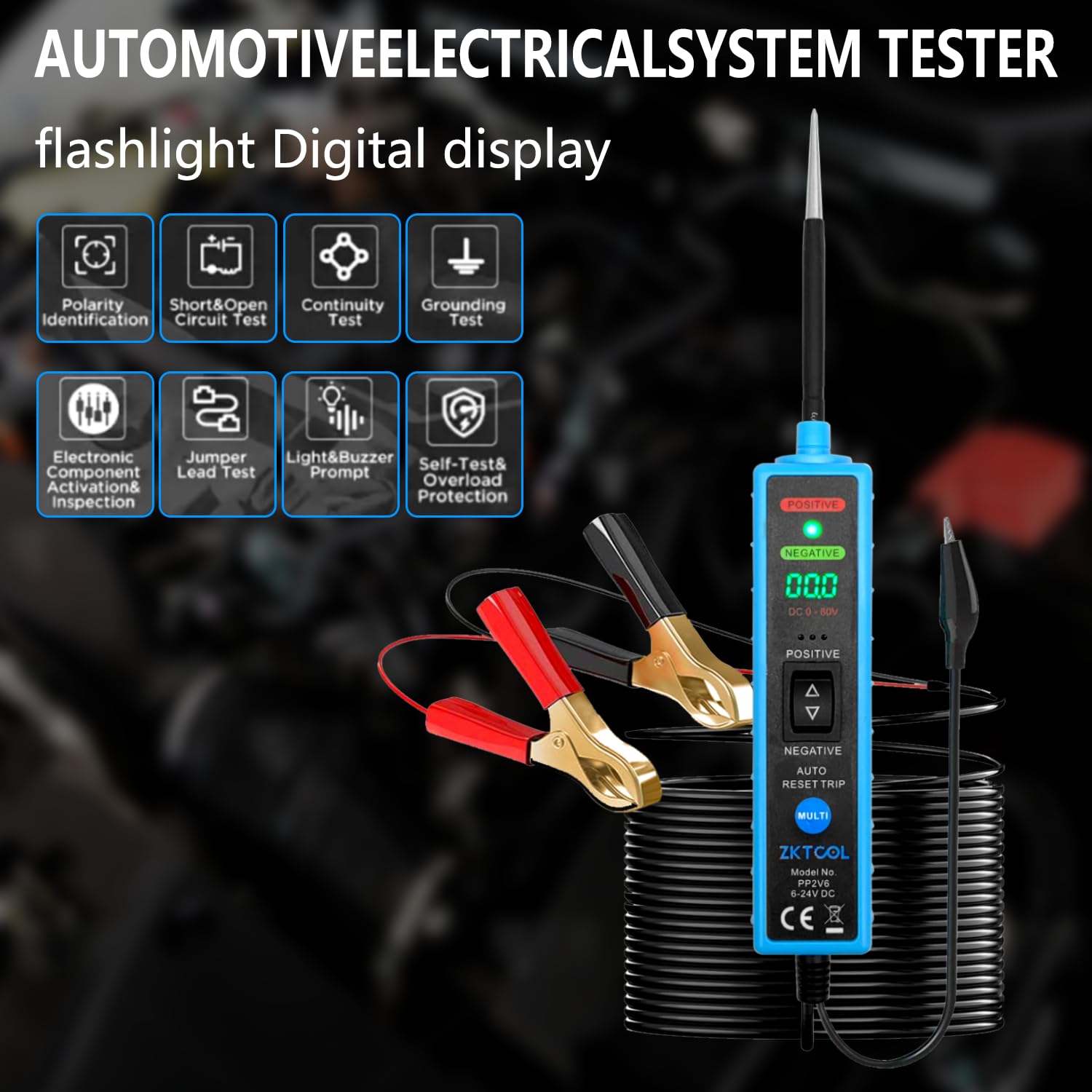
Image 3.1: Key functions and features of the ZKTOOL LED Power Circuit Probe.
Key Features:
- Continuity Testing: Test internal and external vehicle electrical system components.
- Voltage Polarity Check: Quickly identify positive and negative polarity using LED indicators.
- Component Activation: Safely activate internal and external vehicle electrical components.
- Circuit Diagnostics: Verify relays, diodes, fuses, circuit continuity, lights, and motors.
- Fault Location: Locate short circuits and identify bad grounds.
- Voltage Measurement: Measure DC voltages from 6V to 24V.
- Enhanced Safety: Designed to protect the vehicle's computer board from damage.
- Pointed Probe: Easily pierce wires and access narrow areas.
- Backlit LED Screen: Ensures clear visibility of measurements in various lighting conditions.
- Flashlight Function: Integrated flashlight for improved visibility in dark work areas.

Image 3.2: Advantages of the ZKTOOL Upgraded Probe Tester, highlighting the LCD display, extended probe, and copper clamps.

Image 3.3: The integrated flashlight and digital display for enhanced usability in low-light conditions.
4. Setup
Before using the ZKTOOL LED Power Circuit Probe, ensure proper connection to the vehicle's power source.
- Connect the Power Clips:
- Connect the Red Crocodile Clip to the positive (+) terminal of the vehicle's battery.
- Connect the Black Crocodile Clip to the negative (-) terminal or a good chassis ground point.
- Verify Power: Once connected, the device's digital display should illuminate, indicating it is powered on and ready for use.
- Protective Cap: Remove the protective cap from the probe tip before use. Replace it after use to prevent accidental damage or injury.
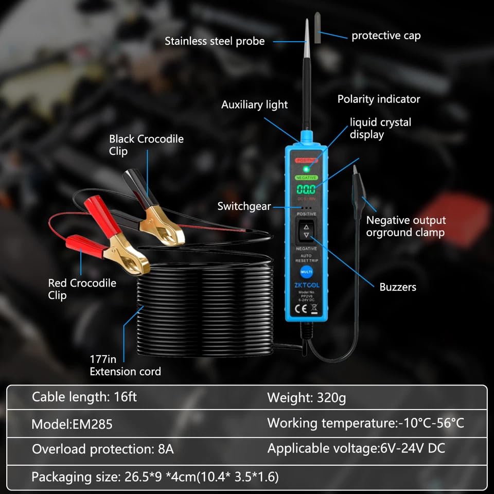
Image 4.1: Detailed view of the ZKTOOL probe components and their labels, including the connection points for the crocodile clips.
5. Operating Instructions
The ZKTOOL LED Power Circuit Probe offers multiple diagnostic functions. Follow these instructions for accurate testing.
5.1. Polarity Identification
This function allows for quick identification of positive and negative polarity in electrical cables and plugs.
- Connect the probe to the vehicle's battery as described in the Setup section.
- Touch the probe tip to the electrical point you wish to test.
- Observe the LED indicator and the digital display:
- If the probe tip touches a positive electrode, the RED LED will illuminate, and the digital display will show the positive voltage.
- If the probe tip touches a negative electrode (ground), the GREEN LED will illuminate, and the digital display will show 0.0V or a very low voltage.

Image 5.1: Visual guide for polarity identification using the LED indicators on the probe.
5.2. Continuity Test
To test for continuity in a circuit or component:
- Ensure the probe is powered.
- Touch the probe tip to one end of the circuit or component.
- If continuity exists, the device will indicate a low resistance reading or a specific continuity signal (e.g., a buzzer sound or a specific display icon).
- For components not connected to the vehicle's power, you may need to provide an external ground or power source to complete the circuit for testing.
5.3. Short & Open Circuit Test
This tool can help locate short circuits and open circuits.
- Short Circuit: When the probe tip touches a shorted circuit, the device may show a direct connection to ground (0V) or trigger an overload protection if current draw is excessive.
- Open Circuit: An open circuit will typically show no voltage reading or no continuity.
5.4. Grounding Test
To check for good ground connections or identify bad grounds:
- Connect the red clip to a known positive voltage source.
- Touch the probe tip to the ground point you wish to test.
- A good ground will typically show a 0V reading and the GREEN LED will illuminate. A bad ground may show a fluctuating voltage or no clear ground indication.
5.5. Electronic Component Activation & Inspection
The probe can safely activate components for testing.
- Connect the probe to the vehicle's battery.
- Touch the probe tip to the positive terminal of the component you wish to activate (e.g., a motor, light bulb).
- Use the appropriate switch on the probe (if available, or by momentarily touching the positive/negative output) to supply power or ground to the component. Observe if the component functions correctly.
- Caution: Ensure the component is rated for the voltage supplied (6-24V DC) and does not draw excessive current to avoid damaging the component or triggering the probe's overload protection.
5.6. Jumper Lead Test
The probe can act as a jumper lead to provide power or ground to components.
- Connect the probe to the vehicle's battery.
- Use the probe tip to supply positive (+) or negative (-) voltage to a component by pressing the corresponding switch on the device.
- This is useful for testing components directly without running additional wires.
5.7. Light & Buzzer Prompt
The device provides visual (LEDs) and audible (buzzer) feedback for various tests, enhancing user awareness.
- Red LED: Indicates positive voltage.
- Green LED: Indicates negative voltage (ground).
- Buzzer: May sound for continuity, short circuits, or other specific conditions depending on the test mode.
5.8. Self-Test & Overload Protection
The ZKTOOL probe includes built-in safety features.
- Self-Test: Upon power-up, the device performs a self-test to ensure proper functionality.
- Overload Protection: The device features an 8A overload protection. If the current drawn through the probe exceeds 8A, the protection will activate to prevent damage to the tool or the vehicle's electrical system. The device will automatically reset once the overload condition is removed.
6. Maintenance
Proper maintenance ensures the longevity and accuracy of your ZKTOOL LED Power Circuit Probe.
- Cleaning: Wipe the device with a soft, dry cloth after each use. Do not use abrasive cleaners or solvents.
- Storage: Store the probe in a clean, dry place, away from direct sunlight and extreme temperatures. Ensure the protective cap is on the probe tip.
- Cable Inspection: Regularly inspect the power cable and crocodile clips for any signs of damage, fraying, or corrosion. Replace if necessary.
- Battery (if applicable): While the device is powered by the vehicle's battery, ensure the vehicle's battery is in good condition for accurate readings.
7. Troubleshooting
If you encounter issues with your ZKTOOL LED Power Circuit Probe, refer to the following common problems and solutions:
| Problem | Possible Cause | Solution |
|---|---|---|
| Device does not power on. |
|
|
| Inaccurate voltage readings. |
|
|
| Overload protection triggers frequently. |
|
|
| LEDs not indicating polarity correctly. |
|
|
8. Specifications
| Brand | ZKTOOL |
| Model | ZKEU650 |
| Power Source | Battery Powered (via vehicle's 6-24V DC system) |
| Operating Voltage Range | DC 6V - 24V |
| Overload Protection | 8A |
| Measurement Type | Multimeter functions (Voltage, Continuity, Polarity) |
| Compliant Specifications | CE Marked, RoHS Compliant |
| Cable Length | 16 ft (approx. 4.8 meters) |
| Weight | 320g |
| Working Temperature | -10°C to 56°C |
| Compatible Devices | Vehicle electrical systems (not for smartphones or computers) |
| UPC | 753873373497 |
| Country of Origin | China |
9. Warranty and Support
Specific warranty information is not provided in the product details. For warranty claims, technical support, or service inquiries, please contact ZKTOOL customer service directly through their official website or the retailer where the product was purchased.
Please have your product model number (ZKEU650) and purchase details ready when contacting support.