1. Introduction
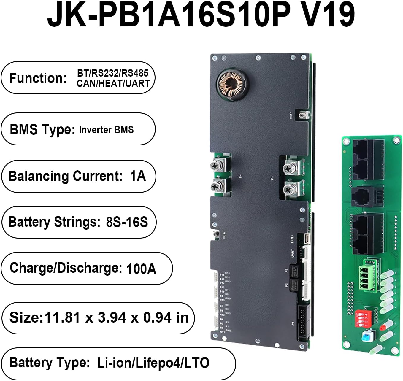
The JKBMS Inverter BMS JK-PB1A16S10P V19 is a sophisticated Battery Management System designed for home energy storage and solar applications. This V19 version includes an additional UART port for enhanced display capabilities, allowing detailed monitoring of parallel battery packs. It supports various battery chemistries including LiFePO4, Li-ion, and LTO, offering robust protection and communication features essential for reliable power systems.
Key Features
- Enhanced Safety: Comprehensive protection against overcharge, over-discharge, overcurrent, short circuit, and reverse connection.
- Versatile Application: Suitable for solar energy systems, home batteries, telecom base stations, and backup power.
- Advanced Communication: Features UART for new display, CAN, RS485, RS232, and Bluetooth app/PC configuration.
- Parallel Expansion: Supports multiple battery packs in parallel with built-in 10A current limiting for safe energy expansion.
- Active Balance: 1A active balancing current for optimal cell health.
- High Precision: Voltage acquisition with ±3mV accuracy and high precision current acquisition.
- Temperature Management: Supports heating function and includes charge/discharge over-temperature and low-temperature protection.
2. Specifications
The following table details the technical specifications of the JKBMS Inverter BMS JK-PB1A16S10P V19.
| Feature | Specification |
|---|---|
| Brand | JKBMS |
| Model | JK-PB1A16S10P V19 |
| Dimensions | 300 x 100 x 24 mm (11.81 x 3.94 x 0.94 inches) |
| Compatible Battery Types | LiFePO4, Li-ion, LTO |
| Active Balance Current | 1A |
| Battery Strings Supported | Li-ion: 7-16S, LiFePO4: 8-16S, LTO: 14S-16S |
| Continuous Discharge/Charge Current | 100A |
| Maximum Discharge Current (MAX 2min) | 200A |
| Communication Interfaces | UART, Bluetooth, RS485, CAN, RS232 |
| Weight | 1.54 pounds |

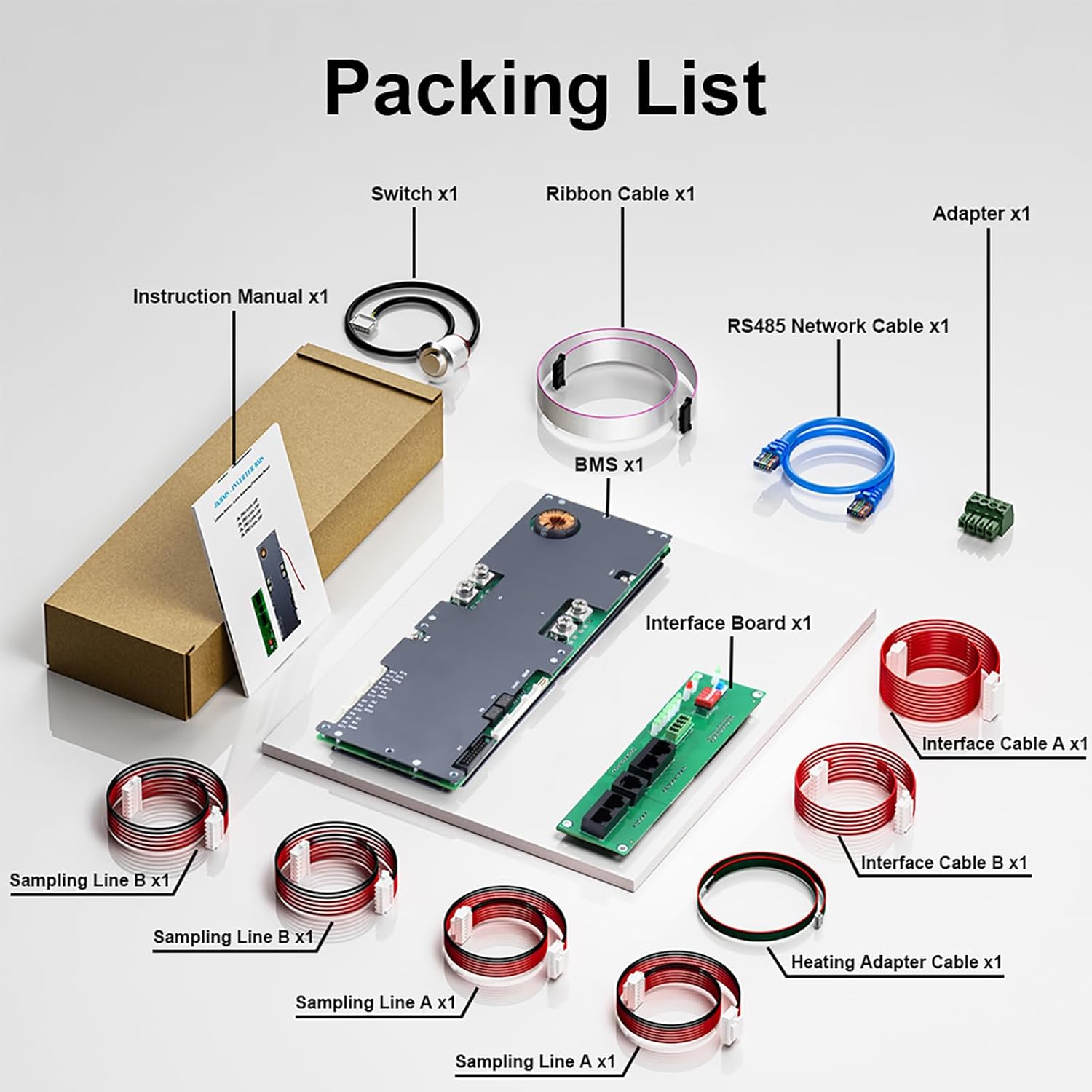
3. Package Contents
Upon opening the package, verify that all the following components are included:
- JK Inverter BMS (Main Protection Board)
- Interface Board
- Communication Cables
- Balancing Cables
- Activation Switch
- Ribbon Cable
- RS485 Network Cable
- Adapter
- Sampling Lines (various)
- Heating Adapter Cable
4. Installation and Wiring
Careful adherence to the wiring sequence is crucial for proper function and safety.
Wiring Sequence
- Solder the B- and P- terminals first.
- Follow with the B+ and P+ terminals.
- Connect battery sampling wires in ascending voltage order.
System Activation
- Power up the system.
- Press the activation button to initiate the BMS.
Disconnecting
- Remove the charger or load first.
- Disconnect battery sampling wires in descending voltage order.
- Remove B+ and P+ terminals, then B- and P- terminals.

5. Operating Instructions
Bluetooth App Operation
The JKBMS can be monitored and configured in real-time using the dedicated "JK BMS" mobile application. This app provides access to battery status, parameters, and allows for adjustments to various settings.
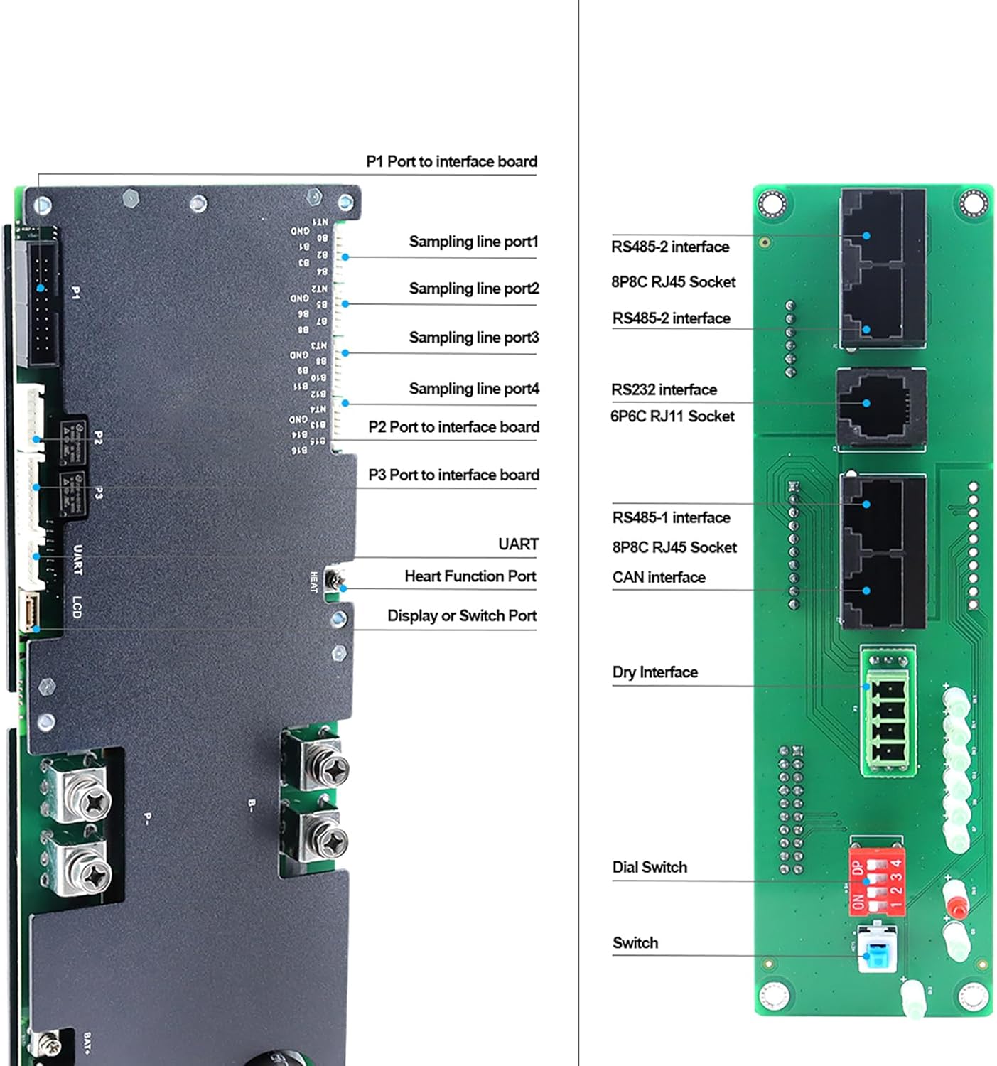
Communication Interfaces
The BMS supports multiple communication protocols for integration with other system components:
- UART: An additional port for connecting to the latest JK display, providing detailed data for parallel battery packs.
- RS485: For robust industrial communication and integration with compatible devices.
- CAN: Supports Controller Area Network communication for automotive and industrial applications.
- RS232: A standard serial communication interface for various devices.
6. Maintenance
To ensure the longevity and optimal performance of your JKBMS Inverter BMS, consider the following maintenance guidelines:
- Regular Inspection: Periodically check all wiring connections for tightness and signs of corrosion or damage.
- Environmental Conditions: Ensure the BMS operates within its specified temperature and humidity ranges to prevent premature wear.
- Software Updates: Check the official JKBMS website or app for any available firmware updates to ensure you have the latest features and bug fixes.
- Cleaning: Keep the BMS free from dust and debris. Use a soft, dry cloth for cleaning; avoid liquids.
7. Troubleshooting
If you encounter issues with your JKBMS, refer to the following basic troubleshooting steps:
- System Not Activating: Verify all wiring connections are correct and secure. Ensure the activation button has been pressed after power-up.
- Communication Issues: Check cable connections for UART, RS485, CAN, or RS232. Ensure Bluetooth is enabled on your mobile device and the "JK BMS" app is correctly installed and paired.
- Protection Triggered: If the BMS shuts down, check the app or display for error codes indicating overcurrent, overvoltage, undervoltage, or over-temperature conditions. Address the root cause (e.g., reduce load, check charger settings, ensure proper ventilation).
- Inaccurate Readings: Confirm that sampling wires are correctly connected and in ascending voltage order.
For more detailed diagnostics, consult the "JK BMS" mobile application or contact customer support.
8. Safety Guidelines
Always observe the following safety precautions when installing, operating, or maintaining the JKBMS Inverter BMS:
- Professional Installation: Installation should be performed by qualified personnel familiar with battery systems and electrical safety.
- Correct Wiring: Follow the wiring instructions precisely. Incorrect wiring can lead to damage, fire, or electric shock.
- Insulation: Ensure all exposed terminals and connections are properly insulated to prevent short circuits.
- Ventilation: Install the BMS in a well-ventilated area to prevent overheating.
- Emergency Procedures: Know how to safely disconnect power in an emergency.
- Avoid Water: Do not expose the BMS to water or excessive moisture.
- Tool Safety: Use insulated tools when working with battery systems.
9. Warranty and Support
The JKBMS Inverter BMS JK-PB1A16S10P V19 comes with a one-year service warranty. For any technical assistance, troubleshooting, or warranty claims, please contact JKBMS dedicated customer support. Real-time monitoring and configuration are also available through the "JK BMS" mobile app.


