1. Introduction
The HLTNC YL586K Series Vector VFD Frequency Converter is an advanced industrial control device designed for precise and efficient motor speed regulation. This inverter is suitable for a wide range of applications requiring variable frequency drive, including CNC machinery, 3D printers, textile equipment, and cutting machines. This manual provides essential information for the safe installation, operation, and maintenance of your 1.5KW, 220V unit, ensuring optimal performance and longevity.
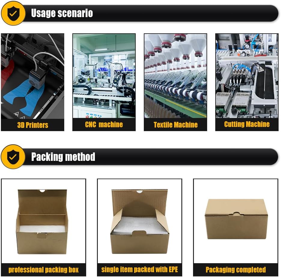
Image 1.1: The HLTNC YL586K VFD is suitable for various industrial applications such as 3D printers, CNC machines, textile machines, and cutting machines, providing precise motor control.
2. Safety Information
Read all safety instructions carefully before installation, operation, or maintenance. Failure to comply with these instructions may result in personal injury or equipment damage.
- Electrical Hazard: Ensure all power is disconnected before performing any wiring or maintenance. Only qualified personnel should perform electrical work.
- Grounding: The inverter must be properly grounded to prevent electric shock.
- Capacitor Discharge: Wait at least 5 minutes after disconnecting power for internal capacitors to discharge before touching any components. Verify with a voltmeter.
- Environmental Conditions: Do not operate the inverter in environments with excessive dust, corrosive gases, flammable materials, or direct sunlight.
- Overload Protection: Do not exceed the rated current or power of the inverter and connected motor.
- Ventilation: Ensure adequate ventilation around the inverter to prevent overheating.
3. Product Overview
The HLTNC YL586K VFD is designed for robust performance and ease of use. It features a compact design with an intuitive digital control panel.

Image 3.1: Various views of the HLTNC YL586K VFD, illustrating its physical dimensions and design from the front, side, top, and bottom.
3.1 Control Panel and Key Functions
The digital control panel provides access to all operational parameters and settings.
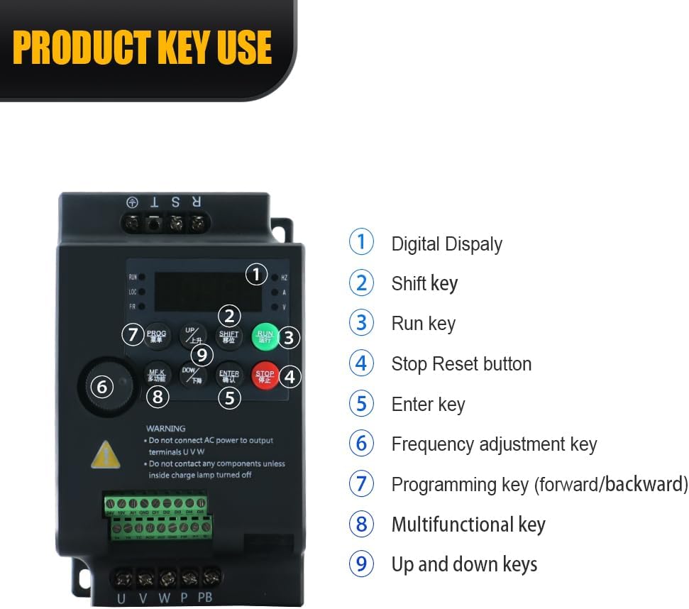
Image 3.2: Detailed view of the HLTNC YL586K VFD control panel, indicating the digital display and the functions of its nine keys for operation and programming.
- Digital Display: Shows operational status, frequency, and parameter values.
- Shift Key: Used to move the cursor during parameter setting.
- Run Key: Initiates motor operation.
- Stop/Reset Button: Stops motor operation and resets fault conditions.
- Enter Key: Confirms parameter selections and settings.
- Frequency Adjustment Key: Adjusts the output frequency.
- Programming Key (Forward/Backward): Accesses and navigates through programming menus.
- Multifunctional Key: Provides additional functions depending on the menu.
- Up and Down Keys: Adjusts parameter values or navigates menu options.
3.2 Product Display Video
Video 3.1: An official product video demonstrating the physical appearance and components of the HLTNC YL586K Series Inverter.
4. Setup and Installation
Proper installation is crucial for the safe and reliable operation of the VFD. Refer to the wiring diagram and follow all local electrical codes.
4.1 Mounting
- Mount the inverter vertically on a stable, non-flammable surface.
- Ensure sufficient clearance (at least 10 cm) around the unit for proper airflow and heat dissipation.
- Avoid mounting near heat sources or in direct sunlight.
4.2 Electrical Connections
All wiring must be performed by a qualified electrician. Ensure the main power supply is disconnected before making any connections.

Image 4.1: Comprehensive wiring diagram for the HLTNC YL586K VFD, detailing connections for power input, motor output, control signals, and optional components like braking resistors.
- Power Input (L, N): Connect the single-phase 220V AC power supply to the L and N terminals.
- Motor Output (U, V, W): Connect the three-phase motor to the U, V, and W terminals. Ensure correct phase sequence.
- Grounding (PE): Connect the ground wire to the PE terminal. This is critical for safety.
- Control Terminals: Connect external control signals (e.g., start/stop, speed reference, emergency stop) to the designated control terminals as per your application requirements. Refer to the detailed product manual for specific terminal functions and programming.
- Braking Resistor (PB): If a braking resistor is used, connect it to the PB terminals.
5. Operating Instructions
Once installed and wired correctly, the inverter can be operated using the control panel.
5.1 Basic Operation
- Power On: Apply power to the inverter. The digital display will illuminate.
- Set Frequency: Use the Frequency Adjustment Key or Up/Down keys to set the desired output frequency.
- Start Motor: Press the RUN key to start the motor. The motor will accelerate to the set frequency.
- Stop Motor: Press the STOP/RESET button to stop the motor. The motor will decelerate and stop.
5.2 Parameter Programming
The inverter has numerous programmable parameters to customize its operation. Refer to the comprehensive programming guide (usually provided with the product or available online) for detailed instructions on setting specific parameters such as acceleration/deceleration times, motor parameters, and control modes.
- Press the PROG key to enter the parameter setting mode.
- Use the Up/Down keys to navigate through parameter groups and individual parameters.
- Use the SHIFT key to move the cursor when editing values.
- Press the ENTER key to confirm and save changes.
6. Maintenance
Regular maintenance ensures the longevity and reliable operation of your VFD.
- Cleaning: Periodically clean the inverter's exterior and ventilation openings to prevent dust accumulation, which can hinder heat dissipation. Use a soft, dry cloth. Do not use liquid cleaners.
- Inspection: Regularly inspect wiring connections for tightness and signs of damage or corrosion. Check for any unusual noises or odors during operation.
- Environmental Check: Ensure the operating environment remains within the specified temperature and humidity ranges.
- Fan Check: Verify that the cooling fan is operating correctly and is free from obstructions.
7. Troubleshooting
If you encounter issues, refer to the table below for common problems and their solutions. For complex issues, contact technical support.
| Problem | Possible Cause | Solution |
|---|---|---|
| Motor does not start | No power supply; Wiring error; Emergency stop active; Parameter settings incorrect. | Check power connections; Verify wiring against diagram; Release emergency stop; Review parameter settings. |
| Inverter displays fault code | Overcurrent; Overvoltage; Overheat; Motor overload. | Refer to the fault code list in the detailed manual for specific actions. Address the underlying cause (e.g., reduce load, improve ventilation). |
| Motor speed unstable | Poor grounding; Interference; Incorrect PID settings. | Check grounding; Ensure proper shielding for control wiring; Adjust PID parameters if applicable. |
| Excessive noise or vibration | Motor imbalance; Mechanical issues; Incorrect carrier frequency. | Inspect motor and load for mechanical issues; Adjust carrier frequency parameter if necessary. |
8. Specifications
Key technical specifications for the HLTNC YL586K Series Vector VFD Frequency Converter (1.5KW, 220V model).
| Feature | Specification |
|---|---|
| Model Name | YL586K |
| Wattage | 1.5 KW |
| Power Source | AC Powered |
| Input Voltage | Single-phase 220V AC (100-120V AC for other variants) |
| Output Voltage | Three-phase 0-220V AC (0-120V AC for other variants) |
| Output Frequency | Up to 3200Hz |
| Recommended Uses | 3D Printers, CNC Machines, Cutting Machines, Textile Machines |
| Brand | LCRHLCNC |
| Item Weight | 2.2 pounds (approx. 1 kg) |
| Package Dimensions | 5.91 x 3.94 x 3.94 inches |
| Operating Temperature | -25°C to 55°C (-13°F to 131°F) |
9. Warranty and Support
For warranty information, technical support, or service inquiries, please refer to the documentation included with your product or contact the manufacturer directly. Ensure you have your product model and serial number available when seeking support.

