1. Introduction
This manual provides detailed instructions for the assembly, operation, and maintenance of your ICONSPORTSS 4WD DIY Electric Axle Kit (Model: ICOTK206TK155TD529). This comprehensive kit is designed for custom electric vehicle projects such as go-karts, ATVs, golf carts, and drift trikes. Please read this manual thoroughly before beginning assembly or operation to ensure proper installation and safe use of all components.
2. Safety Information
WARNING: This kit involves high-voltage electrical components and mechanical systems. Improper assembly or use can result in serious injury or death. Professional installation is highly recommended.
- Always wear appropriate personal protective equipment (PPE), including safety glasses and gloves, during assembly and maintenance.
- Ensure the power source (battery) is disconnected before performing any electrical connections or maintenance.
- Verify all electrical connections are secure and properly insulated to prevent short circuits.
- Do not operate the vehicle in unsafe conditions or without proper training.
- Regularly inspect all components for wear, damage, or loose connections.
- Keep hands and clothing clear of moving parts during operation.
- This kit is intended for off-road use in controlled environments. Adhere to all local regulations regarding vehicle construction and operation.
3. Package Contents
Carefully unpack all components and verify against the list below. If any items are missing or damaged, contact your supplier immediately.

Image 3.1: Overview of all kit components.
- 2x 72V 1500W Brushless Differential Motors
- 1x 40-inch Rear Axle Assembly
- 1x Front 4WD Axle Assembly
- Front Swing Arm Suspension Components (Upper and Lower Swing Arms)
- 4x Tie Rod Ends
- Disc Brake Calipers (Front and Rear)
- Brake Lines and Master Cylinder
- 7-inch Wheels (Quantity as specified by order)
- 2x Motor Controllers
- Wiring Harness with Ignition Key, 3-Speed Switch, Forward/Reverse Control, Brake Switch, Air Safety Switch, Power Indicator, and Throttle Pedal
- Mounting Hardware and Accessories
4. Setup and Assembly
Follow these steps for the proper assembly of your electric axle kit. Refer to the provided images for visual guidance.
4.1. Rear Axle Assembly

Image 4.1.1: Rear Axle Dimensions. Total length 1020mm, effective length 790mm.
- Mount the 40-inch rear axle assembly to your vehicle's frame using appropriate brackets and hardware (not included). Ensure it is centered and securely fastened.
- Attach the rear wheels to the axle shafts.
4.2. Front Axle and Suspension Assembly

Image 4.2.1: Front Suspension Assembly Example.

Image 4.2.2: Front Axle Components and Dimensions. Universal joint shaft length 430-485mm.
- Install the front swing arm suspension components (upper and lower swing arms) onto your vehicle's frame.
- Assemble the front 4WD axle components, including the universal joint shafts and bearing housings, as shown in Image 4.2.2.
- Connect the tie rod ends to the steering mechanism and suspension arms.
- Attach the front wheels to the assembled front axle.
4.3. Motor Installation
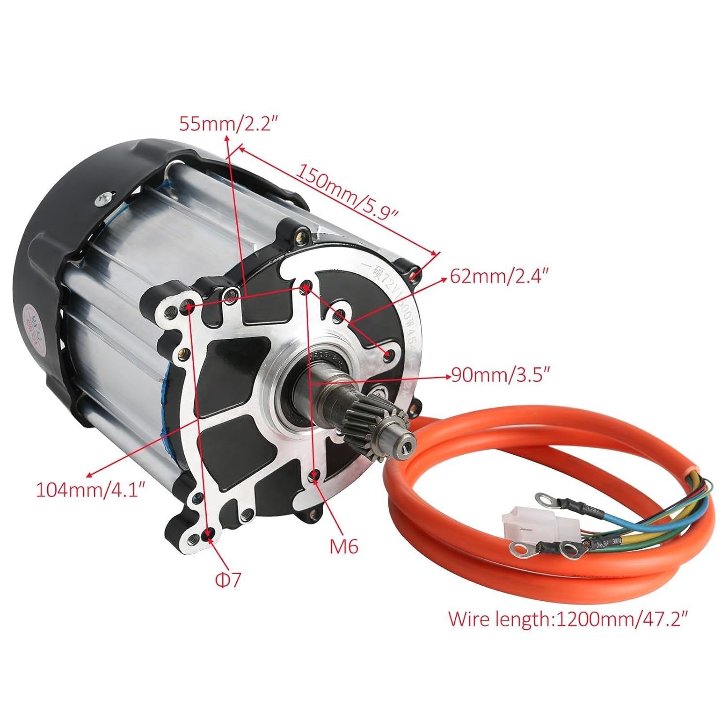
Image 4.3.1: Motor Dimensions. Length 150mm/5.9", Diameter 104mm/4.1".
- Mount the two 72V 1500W brushless differential motors securely to the designated mounting points on the front and rear axle assemblies. Ensure proper alignment with the drive shafts.
- Secure all mounting bolts.
4.4. Brake System Installation

Image 4.4.1: Brake System Components and Dimensions. Cable lengths 520mm/20.47" and 1200mm/47.24".
- Install the disc brake calipers onto the front and rear wheel hubs.
- Connect the brake lines from the calipers to the master cylinder. Ensure all connections are tight to prevent fluid leaks.
- Mount the brake pedal and master cylinder in an accessible location.
- Bleed the brake system according to standard hydraulic brake procedures to remove any air.
4.5. Electrical Connections

Image 4.5.1: Motor Controller Wiring Diagram.
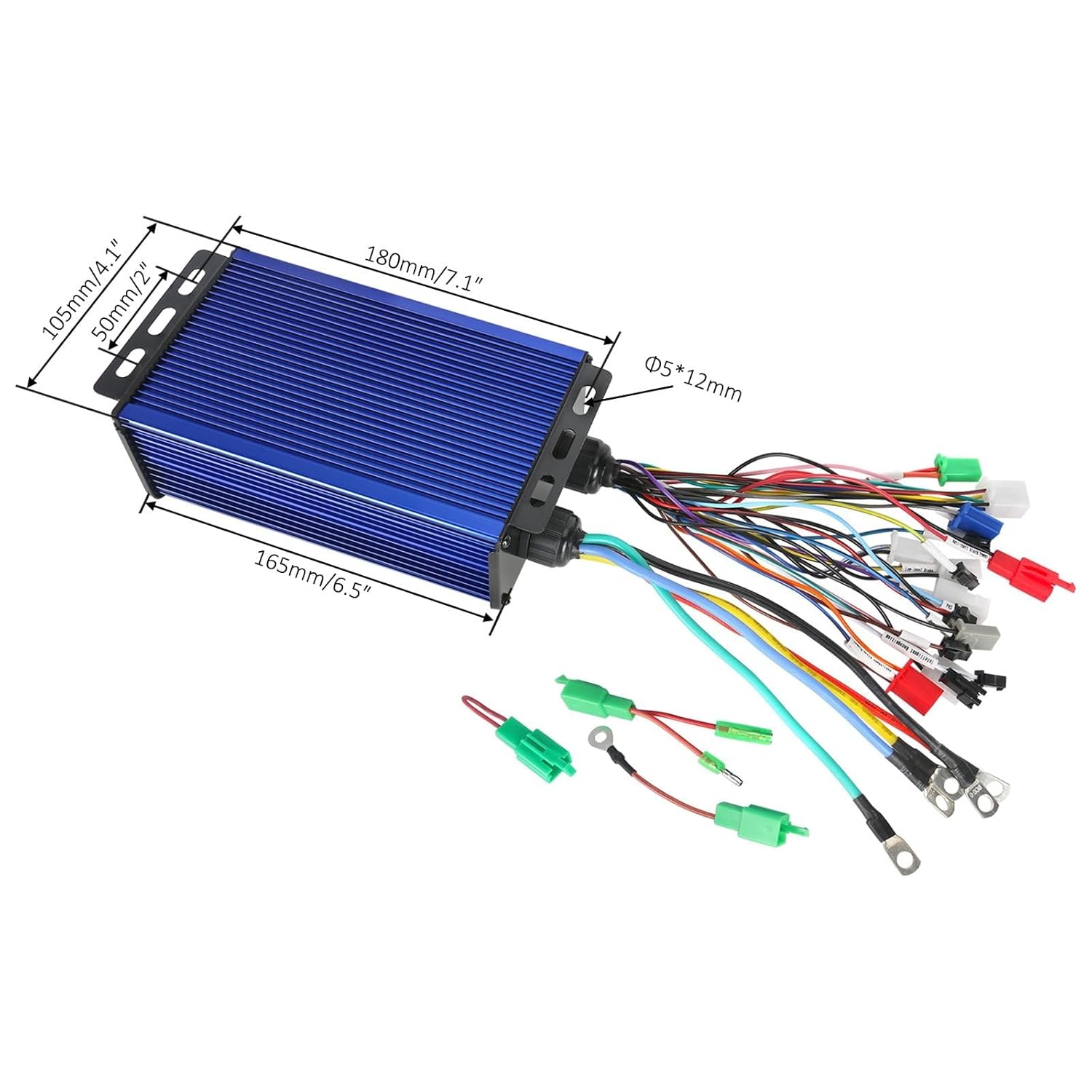
Image 4.5.2: Motor Controller Dimensions. Length 180mm/7.1", Width 105mm/4.1", Height 50mm/2".
- Mount the two motor controllers in a protected, well-ventilated area.
- Refer to Image 4.5.1 for the detailed wiring diagram. Connect the motor phase wires, Hall sensor wires, and battery positive/negative terminals to each controller.
- Connect the main wiring harness components: ignition key, 3-speed switch, forward/reverse switch, throttle pedal, brake switch, and power indicator.
- Ensure all connections are tight, correctly polarized, and insulated to prevent electrical hazards.
- Connect the main power wires from the controllers to your 72V battery pack (battery not included). Double-check polarity before connecting.
- Perform a preliminary check of all electrical connections before applying power.
4.6. Wheel Installation

Image 4.6.1: Wheel Dimensions. Diameter 425mm/16.73", Width 425mm/6.49".
- Mount the 7-inch wheels onto the front and rear axle hubs.
- Ensure lug nuts are tightened to the manufacturer's specifications.
5. Operating Instructions
Once assembly is complete and all safety checks are performed, you can begin operating your vehicle.
- Pre-Operation Check: Before each use, inspect the vehicle for any loose bolts, damaged wiring, proper tire pressure, and functional brakes. Ensure the battery is adequately charged.
- Power On: Insert the ignition key and turn it to the 'ON' position. The power indicator should illuminate.
- Select Speed Mode: Use the 3-speed switch to select your desired speed setting (Low, Medium, High). Start with Low speed for initial testing.
- Select Direction: Use the forward/reverse switch to select the desired driving direction.
- Acceleration: Slowly depress the throttle pedal to accelerate. The vehicle's speed will correspond to the throttle input and selected speed mode.
- Braking: To slow down or stop, release the throttle and apply the brake pedal smoothly.
- Power Off: When finished operating, turn the ignition key to the 'OFF' position and remove the key.
6. Maintenance
Regular maintenance is crucial for the longevity and safe operation of your electric vehicle.
- Monthly Inspection: Check all nuts, bolts, and fasteners for tightness. Inspect wiring for fraying or damage.
- Brake System: Regularly check brake fluid levels and the condition of brake pads. Replace worn pads promptly. Bleed brakes if performance degrades.
- Tires: Maintain correct tire pressure as specified by the tire manufacturer. Inspect tires for wear and damage.
- Axles and Bearings: Inspect axle shafts and bearings for any signs of wear or excessive play. Lubricate moving parts as recommended by component manufacturers.
- Electrical System: Keep battery terminals clean and tight. Ensure controllers and motors are free from dirt and debris. Avoid exposing electrical components to excessive moisture.
- Battery Care: Follow the battery manufacturer's guidelines for charging, discharging, and storage to maximize battery life.
7. Troubleshooting
This section addresses common issues you might encounter.
| Problem | Possible Cause | Solution |
|---|---|---|
| Vehicle does not power on | Battery discharged; Ignition key off; Loose battery connection; Blown fuse/circuit breaker | Charge battery; Turn ignition key on; Check and tighten battery terminals; Inspect and replace fuse/reset breaker |
| Motor not running | Throttle not engaged; Forward/reverse switch in neutral; Controller error; Motor wiring issue | Depress throttle; Select forward or reverse; Check controller error codes (if available); Inspect motor phase and Hall sensor wiring |
| Poor braking performance | Low brake fluid; Air in brake lines; Worn brake pads; Loose caliper mounting | Check and refill brake fluid; Bleed brake system; Replace brake pads; Tighten caliper bolts |
| Unusual noises from axles/motors | Loose components; Worn bearings; Lack of lubrication; Debris in drivetrain | Inspect and tighten all fasteners; Check bearings for play and replace if necessary; Lubricate moving parts; Clean drivetrain components |
8. Specifications
| Feature | Specification |
|---|---|
| Model Number | ICOTK206TK155TD529 |
| Brand | ICONSPORTSS |
| Motor Type | Brushless Differential Motor |
| Motor Voltage | 72V |
| Motor Power | 1500W (each) |
| Motor RPM | Up to 4800 RPM |
| Motor Torque | 3.3Nm (each) |
| Gear Ratio | 9.5:1 |
| Rear Axle Length | 40 inches (1020mm) |
| Wheel Size | 7 inches |
| Material | Carbon Steel |
| Horsepower | 25 Horsepower (total, estimated) |
9. Warranty and Support
For warranty information and technical support, please refer to the documentation provided at the time of purchase or contact ICONSPORTSS directly through their official channels. Keep your purchase receipt and model number (ICOTK206TK155TD529) readily available when seeking support.