1. Introduction
This manual provides essential information for the safe and effective use of the Generic AC-DC Isolated Switching Power Supply Board. This compact module is designed to convert a wide range of AC or DC input voltages into a stable 12V DC output, suitable for various electronic applications. Please read this manual thoroughly before installation and operation.
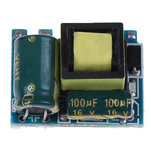
Image 1.1: Top view of the AC-DC Isolated Switching Power Supply Board, showing the main components including capacitors and transformer.
2. Specifications
The following table details the technical specifications of the AC-DC Isolated Switching Power Supply Board:
| Parameter | Value |
|---|---|
| Module Size | 23.5mm x 16mm x 13.5mm (approx.) |
| Input Voltage | AC 55V-277V / DC 70V-390V |
| Output Voltage | DC 12V |
| Maximum Output Current | 300mA |
| Minimum Output Current | 0mA |
| Output Indicator | 1mA / Red light |
| Output Ripple | 60mV |
| Output Power | 3.6W |
| Efficiency | Approximately 80% |
| Working Temperature | -20°C to +70°C |
3. Features
This power supply board incorporates several features for reliable operation:
- Comprehensive Protection: Includes over-voltage protection, over-current protection, over-temperature protection, over-power protection, and short circuit protection.
- Compact Design: Small in size, allowing for integration into various projects with limited space.
- Quality Construction: Fine workmanship ensures good performance and durability.
- Extended Service Life: Designed for long-term reliability.
4. Setup and Installation
Proper installation is crucial for the safe and correct operation of the power supply board. Always ensure power is disconnected before making any connections.
4.1 Safety Precautions
- Ensure all power sources are disconnected before handling the board.
- Avoid touching components while the board is powered, as high voltages may be present.
- Install the board in an enclosure that provides adequate ventilation and protection from environmental factors.
- Observe correct polarity for input and output connections.
4.2 Connection Instructions
Refer to the image below for input and output terminal identification.
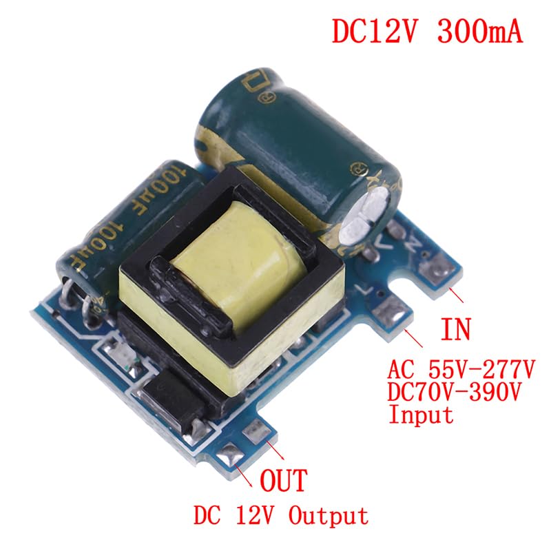
Image 4.1: Close-up of the power supply board showing clearly labeled 'IN' for input and 'OUT' for output terminals. The input accepts AC 55V-277V or DC 70V-390V, and the output provides DC 12V.
- Input Connection: Connect your AC (55V-277V) or DC (70V-390V) power source to the terminals labeled 'IN'. Ensure correct polarity if using a DC input (L for positive, N for negative, though for AC it's line and neutral).
- Output Connection: Connect your 12V DC load to the terminals labeled 'OUT'. Observe the '+' and '-' markings for correct polarity.
- Verification: Double-check all connections before applying power.
5. Operating Instructions
Once properly installed and connected, the power supply board operates automatically.
- Apply the specified input voltage (AC 55V-277V or DC 70V-390V) to the 'IN' terminals.
- The board will convert the input to a stable 12V DC output.
- An output indicator (red light) will illuminate when the output is active, indicating the presence of 12V DC.
- Ensure the total current drawn by your load does not exceed the maximum output current of 300mA to prevent damage to the board or connected devices.
6. Maintenance
The AC-DC Isolated Switching Power Supply Board is designed for minimal maintenance. However, observing the following guidelines can help ensure its longevity:
- Environmental Conditions: Operate the board within its specified working temperature range (-20°C to +70°C). Avoid exposure to excessive moisture, dust, or corrosive environments.
- Cleaning: If necessary, gently clean the board with a soft, dry brush or compressed air to remove dust. Ensure the board is powered off and disconnected from all sources before cleaning. Do not use liquids.
- Inspection: Periodically inspect connections for tightness and signs of wear or corrosion.
7. Troubleshooting
If you encounter issues with the power supply board, consider the following troubleshooting steps:
- No Output Voltage / Output Indicator Off:
- Check if the input power source is correctly connected and supplying the specified voltage range.
- Verify that the input terminals are correctly wired (L and N for AC, + and - for DC).
- Ensure there are no short circuits on the output terminals.
- Incorrect Output Voltage:
- Confirm that the load connected is within the 12V DC specification and does not exceed the 300mA maximum current.
- Check for any loose connections or damaged wiring.
- Overheating:
- Ensure adequate ventilation around the board.
- Verify that the output current does not exceed 300mA.
- Reduce the ambient temperature if it exceeds the maximum operating temperature.
- Intermittent Operation:
- Inspect for loose connections or intermittent shorts.
- Check for unstable input voltage.
If problems persist after following these steps, discontinue use and consult a qualified electronics technician.


