1. Product Overview
The SEQURE 200A Brushless ESC (Electronic Speed Controller) model SQESC 14200 Pro is designed for high-performance applications requiring robust power delivery and precise control. It supports 5-14S Lipo batteries and features a 12V 15A BEC with a 5V fan for efficient cooling. This ESC is compatible with AM32 firmware and various signal protocols.
Key Features
- Firmware & Processor: AM32 firmware, STM32G071 processor.
- Power Input: DC 18V-59V (5-14S Lipo).
- Current Capacity: 200A continuous current, 350A peak current.
- Adjustable BEC: 6V, 7.4V, 8.4V, 12V with 15A continuous current and 35A peak current. Includes a 5V 0.5A continuous current fan.
- Signal Protocols: Automatic throttle signal detection, supports Dshot (All), PWM, Oneshot, and Multishot.
- Advanced Settings: Supports RPM specialized signal, throttle calibration, current detection, motor steering, and telemetry signal settings.
- Applications: Suitable for multi-axis UAVs, fixed-wing drones, crop protection aircraft, helicopters, multi-rotor drones, climbing cars, off-road model vehicles, model ships, and surfboards.
2. What's in the Box
- 1 x Electric Speed Controller
- 1 x 5V Fan
- 2 x 4*250mm Black Tie Straps
- 10 x Hexagonal Screws
- 4 x Transparent Heat Shrinkable Sleeves
3. Specifications
| Feature | Detail |
|---|---|
| Model Name | SQESC 14200 Pro |
| Processor | STM32G071 |
| Input Voltage | DC 18V-59V (5-14S Lipo) |
| Continuous Current | 200A |
| Maximum Current | 350A |
| Supported Firmware | AM32 |
| Signal Protocols | Dshot (All), PWM, Oneshot, Multishot, etc. |
| RPM Specialized Signal | BLHeli_32 (NO), AM32 (YES), ESCape32 (YES) |
| Programming Parameter Adjustment | Support |
| Throttle Calibration | Support |
| Timing Angle Setting | Support |
| Current Detection | Support |
| Telemetry Signal | Support |
| Motor Steering Settings | Support |
| RGB LED Color Lights | Support |
| Fan | YES |
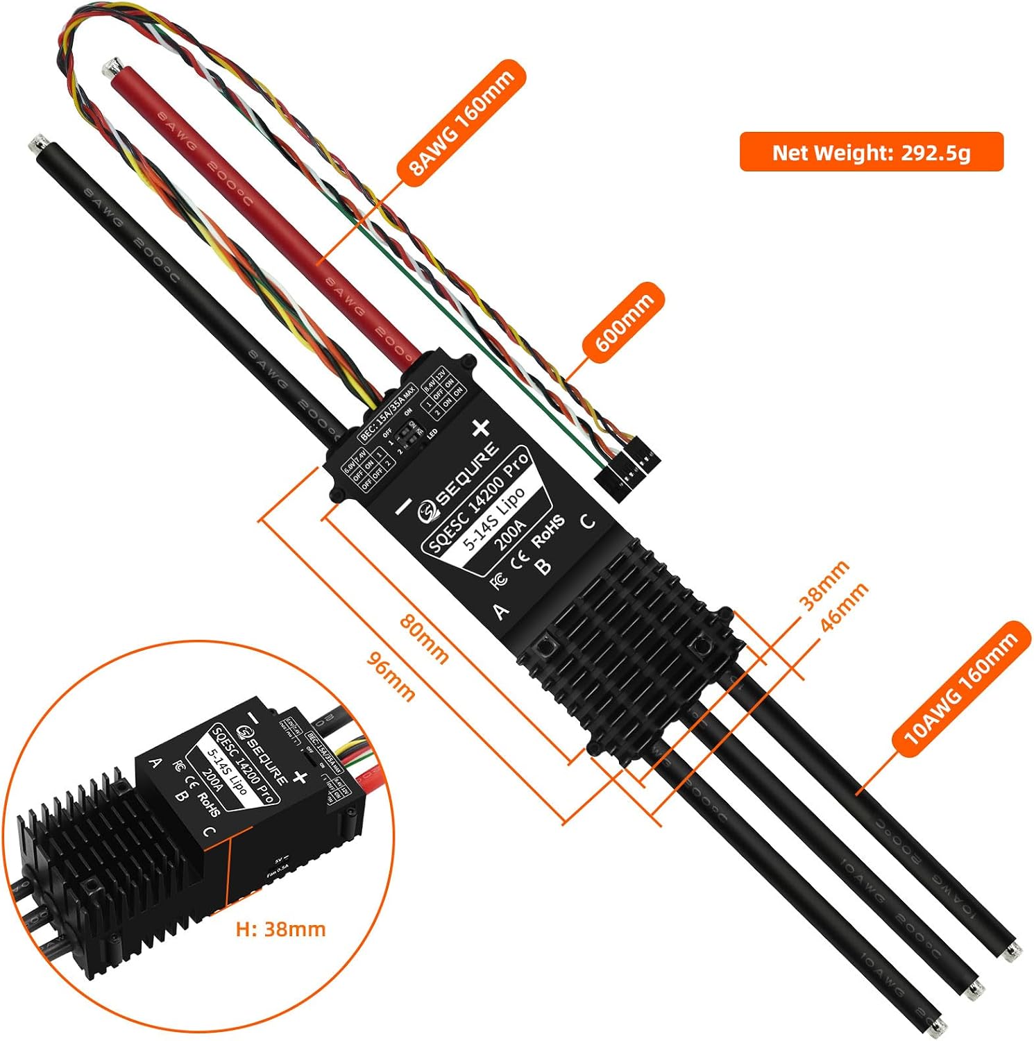
| BEC Details | 6V/7.4V/8.4V/12V 15A continuous, 35A peak current. Fan: 5V 0.5A continuous current. |
| Power Cable | 8AWG Silicone Wire 160mm |
| Motor Cable | 10AWG Silicone Wire 160mm |
| Product Size (L*W*H) | 96mm*46mm*38mm (Not Including Wire) |
| Product Weight | 293g (Including Wire) / 11.4 ounces |
| Application Scenarios | Multi-axis UAV, fixed-wing drones, crop protection aircraft, helicopters, multi rotor drones, climbing cars, off-road model vehicles, model ships, surfboards, water sports products, etc. |
| Product Dimensions | 16.3 x 1.8 x 1.49 inches |
4. Installation and Wiring
Proper installation and wiring are crucial for the safe and effective operation of your ESC. Always ensure power is disconnected before making any connections.
Wiring Diagram

BEC Voltage Adjustment
The 14200 Pro ESC features a dip switch system to adjust the BEC output voltage. Refer to the diagram below for settings.

Heat Dissipation
The ESC is equipped with a metal aluminum radiator for effective heat dissipation, ensuring stable operation under high current loads.

Cable Quality
High-quality twisted pair cables are used to reduce signal interference, ensuring stable and precise transmission.

Installation Hole Position and Dimensions

5. Parameter Configuration and Firmware Upgrade
This section details how to configure parameters and upgrade the firmware using the "Serial Port Connector" program.
Required Software
The "Serial Port Connector" program is required for debugging parameters and firmware upgrades. This program can be downloaded from the official SEQURE website. Navigate to the "BLHeliSuite32 & AM32" section and select the AM32 firmware ESC configuration tool for your operating system (Windows/Linux).
Connection Steps
- Power on the single unit electric tuning.
- Connect the power supply to the ESC.
- Connect the ESC 3-pin cable to the ECL_Link adapter. Ensure 'S' and 'GND' pins are correctly aligned.
- Connect the other end of the ECL_Link adapter to your computer via a data cable.
Software Operation for Parameter Adjustment
- Double-click to open the "Serial Port Connector" program (e.g., "Multi ESC Config Tool 1.82").
- Check "Direct Connect".
- Select the corresponding COM port from the dropdown menu.
- Click "Connect" to establish a connection.
- Click "M1" to read the current parameters from the ESC.
- Modify parameters as required for your application.
- After making changes, click "Save Settings" to apply them to the ESC.
- To confirm the modifications, you can click "M1" again to re-read the parameters.
Software Operation for Firmware Upgrade
- In the "Serial Port Connector" program, click on the "Flash" tab in the top menu.
- Click "Load Firmware".
- Select the corresponding firmware file (e.g., "AM32_SEQURE_4IN1_0071_2.16.hex").
- Click "Flash Firmware" and wait for the upgrade process to complete.
Disconnection Steps
- After completing parameter modification or firmware upgrade, click "Close Connection" in the software.
- Disconnect the power supply from the ESC.
- Disconnect the ECL_Link adapter from your computer.
Instructional Video: Parameter Configuration and Firmware Upgrade
This video demonstrates the process of connecting the SEQURE ESC to a computer, configuring parameters, and performing a firmware upgrade using the "Serial Port Connector" tool. It covers power-on, cable connections, software navigation, reading/writing parameters, and flashing new firmware.
6. Operating Instructions
Once configured, the ESC is ready for operation. Ensure all connections are secure before powering on your device.
- Connect the ESC to your flight controller or receiver according to your system's wiring diagram.
- Ensure the motor is securely attached and free to rotate.
- Power on your system. The ESC will typically emit a series of beeps indicating initialization.
- Calibrate the throttle range if necessary, following your flight controller's instructions.
- Always perform initial tests at a low throttle in a safe environment.
7. Maintenance
Regular maintenance helps ensure the longevity and optimal performance of your ESC.
- Regularly inspect all wiring for damage or loose connections.
- Keep the ESC clean and free from dust, dirt, and moisture.
- Ensure adequate airflow around the ESC to prevent overheating, especially during demanding operations.
- Check for any signs of physical damage to the heatsink or components.
- Periodically check for firmware updates on the SEQURE official website to ensure optimal performance and access to new features.
8. Troubleshooting
Common Issues and Solutions
- ESC not powering on: Check battery connection and voltage. Ensure the power supply is adequate.
- Motor not spinning or erratic behavior: Verify motor connections (A, B, C phases). Check signal cable connection to the flight controller/receiver. Ensure throttle range is calibrated. Re-check ESC parameters for correct motor type and settings.
- Overheating: Ensure proper ventilation and airflow. Reduce load if consistently overheating. Check for short circuits in motor windings.
- ESC not connecting to software: Confirm ECL_Link adapter is correctly connected to both ESC and computer. Ensure correct COM port is selected in the software. Reinstall USB drivers if necessary.
- Firmware upgrade failure: Ensure a stable connection during the upgrade process. Download the correct firmware file for your ESC model.
9. Warranty and Support
For warranty information, technical support, or further assistance, please visit the official SEQURE website or contact their customer service. Keep your purchase receipt for warranty claims.
Official Website: sequremall.com
Email: info@sequremall.com