1. Introduction
This manual provides essential information for the safe and efficient operation of the HLTNC HS320 Variable Frequency Drive (VFD) Inverter. The HS320 series is designed to control the speed of three-phase AC motors, commonly used for spindle speed control in various applications. Please read this manual thoroughly before installation, operation, or maintenance to ensure proper usage and prevent potential hazards.
The specific model covered in this document is the 1.5KW 220V 0-400Hz variant of the HS320 series.
2. Safety Information
WARNING: Improper installation or operation of this equipment can result in serious injury or death, and damage to the equipment. Always adhere to the following safety guidelines:
- Electrical Hazard: This device operates with high voltage. Only qualified personnel should perform installation, wiring, and maintenance.
- Isolation: Always disconnect the main power supply and wait at least 10 minutes for capacitors to discharge before touching any internal components or performing maintenance. Verify zero voltage with a multimeter.
- Grounding: Ensure proper earth connection for the inverter and the motor to prevent electric shock.
- Mounting: Mount the inverter on a non-combustible surface in a well-ventilated area, away from direct sunlight, excessive dust, corrosive gases, or flammable materials.
- Environmental Conditions: Do not expose the inverter to water or excessive moisture. Operate within specified temperature and humidity ranges.
- Wiring: Use appropriate wire gauges and ensure all connections are secure and correct according to wiring diagrams. Incorrect wiring can cause damage or fire.

Figure 2.1: Close-up view of the HLTNC HS320 VFD control panel, highlighting the display, buttons, and important safety warning labels regarding reading the manual, isolating power, proper grounding, and mounting on a non-combustible surface.
3. Product Overview
3.1 Components
The HLTNC HS320 VFD Inverter consists of the main unit and a detachable control panel. Key components include:
- Main Unit: Houses the power electronics, control board, and cooling system.
- Control Panel: Features a digital display, function buttons (PRG/SET, JOG/ESC, UP, DOWN), and RUN/STOP buttons for direct operation and parameter setting.
- Terminal Block: For connecting input power, motor output, and control signals.

Figure 3.1: Front view of the HLTNC HS320 VFD Inverter, showing the integrated control panel and ventilation grilles.

Figure 3.2: The HLTNC HS320 VFD Inverter shown alongside its remote control panel and the ribbon cable for connection, illustrating the flexibility of operation.
3.2 Specifications (1.5KW 220V Model)
| Parameter | Value |
|---|---|
| Model Number | HS320 |
| Output Power | 1.5KW |
| Input Voltage | 220V (Single Phase or Three Phase, check specific model label) |
| Output Voltage | 3-Phase 0-220V |
| Output Frequency | 0-400Hz |
| Dimensions (L x W x H) | Approximately 0.39 x 0.39 x 0.39 inches (Refer to actual product for precise measurements) |
| Item Weight | Approximately 1.76 ounces (Refer to actual product for precise weight) |
4. Setup
4.1 Mounting
Select a suitable mounting location that is:
- On a non-combustible surface.
- Free from vibrations.
- Well-ventilated to allow for adequate heat dissipation.
- Protected from direct sunlight, dust, moisture, and corrosive substances.
Ensure sufficient clearance around the inverter for airflow and maintenance access.
4.2 Wiring
CAUTION: All wiring must be performed by a qualified electrician in accordance with local and national electrical codes.
- Power Input: Connect the main power supply to the designated input terminals (L1/R, L2/S, L3/T for 3-phase, or L/N for single-phase, depending on model). Ensure the voltage matches the inverter's rating (e.g., 220V).
- Motor Output: Connect the three-phase motor leads to the output terminals (U, V, W).
- Grounding: Connect the ground terminal of the inverter to a reliable earth ground. Also, ensure the motor frame is properly grounded.
- Control Wiring (Optional): If using external control signals (e.g., potentiometer for speed control, external start/stop buttons), connect them to the appropriate control terminals as per the detailed wiring diagram in the full product manual.
After wiring, double-check all connections for tightness and correctness before applying power.
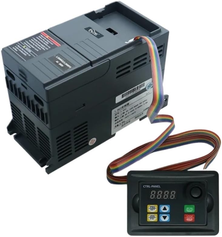
Figure 4.1: The HLTNC HS320 VFD Inverter with its remote control panel and cable, illustrating the potential for remote operation and highlighting the main unit's connection points.
5. Operating Instructions
5.1 Control Panel Functions
- Display: Shows operating frequency, output current, voltage, and parameter codes.
- PRG/SET Button: Enters/exits parameter setting mode, confirms parameter changes.
- JOG/ESC Button: Used for jogging (momentary operation) or exiting a menu without saving changes.
- UP/DOWN Arrows: Navigate through parameters, adjust values.
- RUN Button: Starts the motor.
- STOP/RES Button: Stops the motor, resets fault alarms.
5.2 Basic Operation
- Power On: Apply main power to the VFD. The display will light up.
- Frequency Setting: Use the PRG/SET button to enter parameter mode. Navigate to the frequency setting parameter (refer to the full manual for specific parameter codes). Use UP/DOWN arrows to adjust the desired output frequency (e.g., 0-400Hz). Press PRG/SET to confirm.
- Start Motor: Press the RUN button. The motor will accelerate to the set frequency.
- Stop Motor: Press the STOP/RES button. The motor will decelerate and stop.
- Jog Operation: Press and hold the JOG/ESC button to run the motor at a preset jog frequency. Release to stop.
For advanced functions, parameter settings, and detailed programming, refer to the comprehensive programming manual provided with the product.
6. Maintenance
Regular maintenance ensures the longevity and reliable operation of your VFD. Always disconnect power and wait for capacitor discharge before performing any maintenance.
- Cleaning: Periodically clean the VFD's exterior and ventilation openings to prevent dust accumulation, which can hinder cooling. Use a soft, dry cloth. Do not use liquid cleaners.
- Inspection: Regularly inspect wiring connections for tightness and signs of wear or damage. Check for any unusual noises or odors during operation.
- Environmental Check: Ensure the operating environment remains within specified temperature and humidity limits.
- Fan Check: Verify that the cooling fan (if present) is operating correctly and not obstructed.
7. Troubleshooting
This section provides solutions for common issues. For complex problems or persistent faults, contact technical support.
| Problem | Possible Cause | Solution |
|---|---|---|
| VFD does not power on | No input power; Blown fuse; Incorrect wiring | Check power supply; Inspect fuses; Verify wiring connections. |
| Motor does not run | VFD not in RUN mode; Incorrect frequency setting; Motor wiring error; Overload | Press RUN button; Adjust frequency; Check motor wiring; Reduce load. |
| Overcurrent fault (OC) | Motor overload; Short circuit in motor or wiring; Rapid acceleration/deceleration | Reduce load; Check motor/wiring; Adjust acceleration/deceleration times in parameters. |
| Overvoltage fault (OV) | High input voltage; Rapid deceleration with high inertia load | Check input voltage; Increase deceleration time; Consider braking resistor if applicable. |
| Undervoltage fault (UV) | Low input voltage; Momentary power loss | Check input voltage; Ensure stable power supply. |
| Overheat fault (OH) | Insufficient cooling; Ambient temperature too high; Blocked ventilation | Ensure proper ventilation; Clean heatsink/fan; Reduce ambient temperature. |
After resolving a fault, press the STOP/RES button to clear the alarm before attempting to restart the VFD.
8. Warranty and Support
For information regarding product warranty, technical support, or service, please refer to the documentation included with your purchase or contact the manufacturer/seller directly. Ensure you have your product model number (HS320) and purchase details available when seeking support.


