1. Introduction
This manual provides essential information for the proper installation, operation, and maintenance of the ZHZKPLPPRB FUWEI FSD23-15-AV Analog Voltage Displacement Sensor. This device is an optical-electronic sensor designed for high-accuracy, non-contact linear displacement measurement, featuring an LED digital screen for real-time readings and analog voltage output.
2. Setup and Installation
2.1 Mounting
The FSD23-15-AV sensor is designed for screw fixing. Ensure the mounting surface is stable and free from vibrations. Position the sensor so that its optical path is clear and perpendicular to the target surface for optimal performance. Use appropriate screws to secure the sensor firmly through its designated mounting holes.
2.2 Wiring
Connect the sensor to a compatible power supply and control system according to the wiring diagram provided on the device label. The sensor operates on a 12-24VDC power supply.
- BN (Brown): Power Supply Positive (UB+)
- BU (Blue): Power Supply Negative (0V / Ground)
- BK (Black): Analog Voltage Output
- WH (White): Not used for standard analog voltage output (refer to specific application diagrams if applicable)
Ensure all connections are secure and correctly polarized to prevent damage to the sensor or connected equipment.

Figure 1: Front view of the FSD23-15-AV sensor, showing the LED digital screen, control buttons, and M12 connector with integrated wiring diagram. The diagram illustrates the connection points for power and analog output.
3. Operating Instructions
3.1 Power On
Once wired correctly, apply 12-24VDC power. The LED digital screen will illuminate, displaying the current displacement reading.
3.2 Display and Indicators
- LED Digital Screen: Displays the measured displacement value in millimeters (mm).
- LASER Indicator: Illuminates when the laser emitter is active.
- OUT Indicator: Illuminates when the output signal is active or within a defined range.
3.3 Control Buttons
The sensor features several buttons for configuration and operation:
- ZERO: Used to set the current displacement reading as the zero reference point. Press and hold to activate.
- + / -: Used to adjust parameters or navigate through menu options during configuration.
- SET: Used to enter the configuration menu, confirm selections, or save settings.
- MANUAL: May be used to switch between automatic and manual operating modes or to trigger specific functions.
3.4 Displacement Measurement
Position the target object within the sensor's sensing range (Sn: 10-20mm). The sensor will continuously measure the distance to the target and display it on the LED screen. The analog voltage output will correspond to this measured displacement.
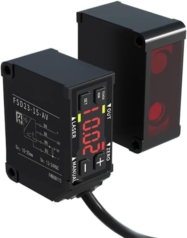
Figure 2: The FSD23-15-AV sensor positioned to measure displacement from a reflective surface, demonstrating its non-contact measurement capability.
4. Maintenance
To ensure long-term reliable operation of your FSD23-15-AV sensor, follow these maintenance guidelines:
- Cleaning: Regularly clean the sensor's optical surfaces with a soft, lint-free cloth. Avoid abrasive materials or harsh chemicals that could scratch the lens or damage the housing.
- Environmental Conditions: Operate the sensor within its specified environmental limits. Protect it from excessive dust, moisture, extreme temperatures, and corrosive substances.
- Cable Inspection: Periodically inspect the connecting cable for any signs of wear, cuts, or damage. Replace damaged cables immediately to prevent electrical hazards or signal loss.
5. Troubleshooting
If you encounter issues with your FSD23-15-AV sensor, refer to the following common problems and solutions:
- No Power/Display Off:
Possible Cause: Incorrect wiring or no power supply.
Solution: Verify that the 12-24VDC power supply is connected correctly to the BN and BU wires and is active. Check for loose connections. - Inaccurate or Unstable Readings:
Possible Cause: Sensor misalignment, dirty optical surface, target surface irregularities, or vibrations.
Solution: Ensure the sensor is securely mounted and properly aligned with the target. Clean the sensor's optical window. Check the target surface for consistency. Minimize vibrations in the operating environment. - No Analog Output:
Possible Cause: Incorrect wiring of the output, sensor not detecting a target, or internal fault.
Solution: Confirm the BK wire is correctly connected to your control system's analog input. Ensure the target is within the sensing range. If the issue persists, contact support. - Buttons Unresponsive:
Possible Cause: Sensor in a locked mode or internal fault.
Solution: Power cycle the device. If buttons remain unresponsive, contact support.
6. Specifications
| Feature | Specification |
|---|---|
| Model Number | FSD23-15-AV |
| Theory | Optical Sensor |
| Type | Optical-Electronics Sensor, Linear Displacement Sensor |
| Mounting Type | Screw fixing |
| Sensing Range (Sn) | 10-20mm |
| Power Supply (Us) | 12-24VDC |
| Spot Size | 0.5 x 0.7mm |
| Linearity | ±0.1% F.S. |
| Package Dimensions | 0.39 x 0.39 x 0.39 inches |
| Item Weight | 1.1 pounds |
| Manufacturer | ZHZKPLPPRB |
7. Warranty and Support
For warranty information, please refer to the terms and conditions provided by your retailer or contact the manufacturer directly. For technical support or further assistance, please reach out to the seller or manufacturer through their official channels.


