1. Introduction
This manual provides detailed instructions for the installation, operation, and maintenance of your Ecostar Energy E701 Non-Programmable Digital Thermostat. This thermostat is designed for conventional single-stage heating and cooling systems (1 Heat/1 Cool) and offers precise temperature control with an easy-to-read green backlit display. Please read this manual thoroughly before installation and use to ensure proper function and safety.
2. Safety Information
Important: Electrical shock hazard. Disconnect power to the heating/cooling system before installing or servicing the thermostat. Failure to do so can result in electrical shock or equipment damage.
Professional Consultation: If you are not experienced with thermostat installation or wiring, it is recommended to consult a qualified HVAC professional to avoid potential malfunction or incompatibility issues. This unit is compatible only with systems using 2 to 5 wires and is not suitable for setups with 6 to 8 wires.
3. Package Contents
Verify that your package contains the following items:
- Ecostar Energy E701 Thermostat
- Installation Manual
- Wire-Labeling Stickers
- Two Screws and Anchors

Image: Contents of the Ecostar Energy E701 Thermostat package, showing the thermostat unit, installation manual, wire labels, and mounting hardware.
4. Setup and Installation
4.1 Compatibility
The Ecostar Energy E701 thermostat is compatible with the following systems:
- Conventional Single-Stage Heating & Cooling Systems (1 Heat/1 Cool)
- Gas, Oil, or Electric Furnaces (1 Heat only)
- Boiler Radiant Heat (1 Heat only)
- Forced-Air Furnaces (1 Heat only)
- Cooling Only systems
- Gas Fireplaces (24V)
- 1H/1C Heat Pump systems without auxiliary heat
Not Compatible With:
- Multistage HVAC systems (1H/2C, 2H/2C)
- Heat pump systems with auxiliary or emergency heat (2H/1C, 4H/2C)
- PTAC units
- 3-wire hydronic (hot water) systems
- Dual fuel/hybrid heating
- Line voltage systems (120–240V electric baseboard heat)
- Mini split systems
- RV air conditioners (including MACH and Roughneck series)

Image: A table detailing compatible systems, number of wires, and required terminal connections for the Ecostar Energy E701 thermostat.
4.2 Pre-Installation Steps
- Turn off Power: Before beginning, turn off the power to your heating and cooling system at the main circuit breaker or fuse box.
- Remove Old Thermostat: Carefully remove the cover of your old thermostat.
- Label Wires: Before disconnecting any wires, use the provided wire-labeling stickers to clearly label each wire according to its terminal designation (e.g., R, C, Y, G, W). This is crucial for correct installation.
- Disconnect Wires: Once labeled, disconnect the wires from the old thermostat terminals.
- Remove Old Mounting Plate: Unscrew and remove the old thermostat's mounting plate from the wall.
4.3 Mounting the New Thermostat
- Position Mounting Plate: Place the Ecostar Energy E701 mounting plate against the wall where you want to install the thermostat. Ensure it is level.
- Mark Drill Holes: Mark the positions for the mounting screws through the holes on the new mounting plate.
- Drill Holes: Drill pilot holes at the marked positions. Insert the provided wall anchors if drilling into drywall.
- Secure Mounting Plate: Feed the labeled wires through the opening in the mounting plate and secure the plate to the wall using the provided screws.
4.4 Wiring Connections
Connect the labeled wires to the corresponding terminals on the Ecostar Energy E701 mounting plate. Refer to the wiring diagrams below for typical system configurations.

Image: The backplate of the Ecostar Energy E701 thermostat showing terminal screw connections and their labels (C, O, B, W, RH, RC, G, Y).
Terminal Designations:
- C: Common 24VAC (system power supply)
- O: Reversing Valve (Cool)
- B: Reversing Valve (Heat)
- W: Heat Relay
- RH: 24VAC Transformer Power (Heat)
- RC: 24VAC Transformer Power (Cool)
- G: Fan Relay
- Y: Cool Relay
Jumper Settings:
- The RH and RC terminals have a factory-installed jumper. Keep this jumper in place if your system uses a single transformer for both heating and cooling.
- If you have a dual transformer system (separate transformers for heating and cooling), remove the RH-RC jumper.

Image: Detailed wiring diagrams for different conventional HVAC system types, illustrating connections to the thermostat terminals.
4.5 Power Options
The E701 thermostat can be powered by either 24VAC (if a C-wire is connected) or by 2x AA batteries.
- 24VAC Power: If your system has a C-wire (Common wire) connected to the 'C' terminal, the thermostat will draw power from your HVAC system.
- Battery Power: If no C-wire is available or connected, the thermostat will operate on 2x AA alkaline batteries (not supplied). The C-wire is only required if 2 AA batteries are not installed.
4.6 Attaching the Thermostat Body
Once wiring is complete, align the thermostat body with the mounting plate and gently push it into place until it snaps securely. Ensure all wires are tucked neatly into the wall opening to prevent interference.
4.7 Initial Power-Up
Restore power to your heating and cooling system at the main circuit breaker. The thermostat display should illuminate.
5. Operation

Image: The Ecostar Energy E701 thermostat's main display, showing current room temperature, set temperature, and system/fan mode indicators.
5.1 Display Overview
The large LCD screen displays the following information:
- Room Temperature: The current ambient temperature.
- Set At: Your desired temperature setting.
- System Mode Indicator: Shows if the system is in Cool, Heat, or Off mode.
- Fan Mode Indicator: Shows if the fan is in On or Auto mode.
- Low Battery Indicator: A battery symbol will flash when batteries need replacement.
5.2 Adjusting Temperature
Use the + (Up) and - (Down) buttons on the right side of the thermostat to adjust your desired set temperature. The temperature control range is 44°F to 90°F (7°C to 32°C).
5.3 System Mode Selection
The SYSTEM switch located at the bottom center of the thermostat allows you to select the operating mode:
- COOL: Activates the cooling system.
- OFF: Turns off both heating and cooling systems.
- HEAT: Activates the heating system.
5.4 Fan Mode Selection
The FAN switch located at the bottom left of the thermostat controls the fan operation:
- ON: The fan runs continuously, regardless of whether the heating or cooling system is active.
- AUTO: The fan runs only when the heating or cooling system is actively operating.
5.5 Backlight Operation
The green backlight illuminates when any button is pressed and remains on for approximately 10 seconds to improve readability in low light conditions. This thermostat does not support a continuously-on backlight.
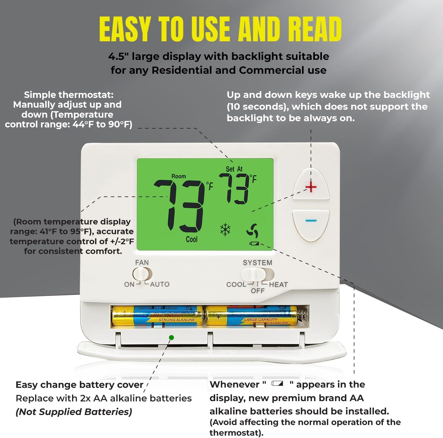
Image: A detailed view of the Ecostar Energy E701 thermostat, highlighting the battery compartment and the clear, backlit LCD display.
5.6 Temperature Swing (Cycle Rate) Adjustment
The temperature swing, also known as cycle rate or differential, determines how frequently your heating/cooling system cycles on and off. A smaller swing setting results in more frequent, shorter cycles, while a larger swing setting results in fewer, longer cycles.
- The swing is adjustable from 0.2°F to 2°F.
- The factory default for heating or cooling is 0.5°F.
- For example, a swing setting of 0.5°F will turn the heating off at approximately 0.5°F above the setpoint and turn the heating on at approximately 0.5°F below the setpoint.

Image: The Ecostar Energy E701 thermostat display showing the adjustable temperature swing setting, here set to 0.5°F for cooling.
6. Maintenance
6.1 Battery Replacement
When the low battery indicator (a flashing battery symbol) appears on the display, it's time to replace the batteries. This thermostat requires 2x AA alkaline batteries.
- Open the battery compartment cover located at the bottom of the thermostat.
- Remove the old batteries.
- Insert two new AA alkaline batteries, ensuring correct polarity (+/-).
- Close the battery compartment cover.
Note: Replace batteries promptly to avoid affecting the normal operation of the thermostat.
6.2 Cleaning
To clean the thermostat, gently wipe the exterior with a soft, damp cloth. Do not use abrasive cleaners or solvents, as these can damage the thermostat's finish or internal components.
7. Troubleshooting
| Problem | Possible Cause | Solution |
|---|---|---|
| Thermostat display is blank. | No power (batteries dead or C-wire disconnected). | Replace batteries or check C-wire connection and circuit breaker. |
| Heating/Cooling system not responding. | Incorrect wiring; system switch in OFF; power off to HVAC. | Verify wiring connections; ensure SYSTEM switch is on HEAT or COOL; check HVAC power. |
| Temperature is inconsistent. | Thermostat location; incorrect temperature swing setting. | Ensure thermostat is not in direct sunlight or near heat sources; adjust temperature swing (cycle rate). |
| Compressor short cycling (turns on/off too quickly). | Compressor delay protection active; temperature swing too small. | Wait 5 minutes for compressor delay to reset; increase temperature swing setting. |
| Fan runs continuously in AUTO mode. | Fan switch set to ON. | Set FAN switch to AUTO. |
8. Specifications
| Feature | Detail |
|---|---|
| Model Name | E701 |
| Brand | Ecostar Energy |
| Control Type | Conventional Single Stage Button Control |
| System Compatibility | 1 Heat / 1 Cool (Single-Stage) |
| Power Source | 24VAC (C-wire) or 2x AA Batteries |
| Voltage | 24 Volts |
| Temperature Range | Display: 41°F to 95°F (5°C to 35°C) Control: 44°F to 90°F (7°C to 32°C) |
| Temperature Accuracy | ±1°F (±0.5°C) |
| Display Type | LCD with Green Backlight |
| Special Features | Fan Control, Low Battery Indicator, Temperature Display, 5-minute Compressor Delay Protection |
| Product Dimensions | 3.8"D x 1.3"W x 4"H (approx.) |
| Material | Plastic |
| Color | White |
9. Warranty and Support
9.1 Warranty Information
Ecostar Energy products are designed for reliability and performance. For specific warranty details, please refer to the warranty card included with your product or visit the official Ecostar Energy website. Keep your proof of purchase for warranty claims.
9.2 Customer Support
If you have any questions, require technical assistance, or encounter issues not covered in this manual, please contact Ecostar Energy customer support. Contact information can typically be found on the product packaging or the official Ecostar Energy website.