1. Introduction
This manual provides detailed instructions for the installation, operation, and maintenance of your VIVOHOME Autoflow Bathroom Exhaust Fan with Light and Humidity Sensor, Model VH1810. Please read this manual thoroughly before installation and use to ensure proper function and safety. Keep this manual for future reference.

Figure 1: VIVOHOME Autoflow Bathroom Exhaust Fan with Light and Humidity Sensor.
2. Safety Information
Always follow basic safety precautions when installing or using this product to reduce the risk of fire, electric shock, or injury to persons.
- WARNING: To reduce the risk of fire, electric shock, or injury to persons, observe the following:
- Use this unit only in the manner intended by the manufacturer. If you have questions, contact the manufacturer.
- Before servicing or cleaning the unit, switch power off at the service panel and lock the service disconnecting means to prevent power from being switched on accidentally. When the service disconnecting means cannot be locked, securely fasten a prominent warning device, such as a tag, to the service panel.
- Installation work and electrical wiring must be done by qualified person(s) in accordance with all applicable codes and standards, including fire-rated construction codes and standards.
- Sufficient air is needed for proper combustion and exhausting of gases through the flue (chimney) of fuel-burning equipment to prevent back-drafting. Follow the heating equipment manufacturer’s guideline and safety standards such as those published by the National Fire Protection Association (NFPA), and the American Society for Heating, Refrigeration and Air Conditioning Engineers (ASHRAE), and the local code authorities.
- When cutting or drilling into wall or ceiling, do not damage electrical wiring and other hidden utilities.
- Ducted fans must always be vented to the outdoors.
- This unit is designed for double insulation, eliminating the need for a ground wire.
3. Package Contents
The VIVOHOME Autoflow Bathroom Exhaust Fan comes with a complete accessory kit for quick and easy installation. Please verify all components against the package contents and hardware list upon unboxing.
- Exhaust Fan Unit with Light and Humidity Sensor
- Remote Control
- Extended Power Cord (20 inches)
- Duct Hose (4.6 ft, Ø4-inch)
- Cutout Template
- Screws
- Duct Clamps
- User Manual

Figure 2: Full Accessory Kit.
4. Product Features
The VIVOHOME Autoflow Bathroom Exhaust Fan is designed for efficiency, durability, and intelligent operation.
- Durable & Efficient: Constructed with corrosion-resistant ABS and PP housing. Features an energy-efficient brushless EC motor with a lifespan of 20,000-30,000 hours, consuming 50% less energy than AC motors. Double insulation design allows for non-grounded wiring.
- Autoflow Design: Equipped with a high-precision humidity sensor for optimal ventilation. Operates at 30 CFM for low humidity (<50% RH), 110 CFM for moderate humidity (50%-80% RH), and 160 CFM for high moisture conditions (>80% RH). The remote control also offers manual adjustment with 6-speed settings.
- Tri-Color Lighting: The integrated light offers three color temperatures (2700K Warm, 4000K Neutral, 5700K Cool White) with 6-level dimming. Includes a bright 1500-Lumen Neutral White setting and a convenient Night Mode (2700K, 200LM).
- Constant Airflow Technology: Unlike traditional fixed-speed fans, this fan self-adjusts its speed to maintain consistent airflow against duct bends, dust buildup, or increased static pressure, ensuring stable and reliable ventilation over time.
- Quiet Operation: The powerful 45W motor operates quietly, with a noise level as low as 0.1 Sone in Nighttime operation and up to 1.5 Sones at maximum speed.

Figure 3: Fan rated for 89-129 sq ft bathrooms.

Figure 4: Constant Airflow Technology maintains consistent performance.
Video 1: Overview of VIVOHOME Bathroom Exhaust Fan with Light & Humidity Sensor features.
5. Setup & Installation
Follow these steps for a safe and efficient installation. Installation may vary based on existing fan setup. Additional materials (not included) may be required.
5.1 Planning & Preparation
- Confirm all components match the parts and hardware list provided in Section 3.
- Safety First: Switch off power at the breaker before you begin any installation work.
- Determine the installation location. The housing measures 8.9 x 8.9 x 5.7 inches, with a white panel of 11.8 x 11.8 inches. The recommended mounting hole is 10.2 x 10.2 inches.
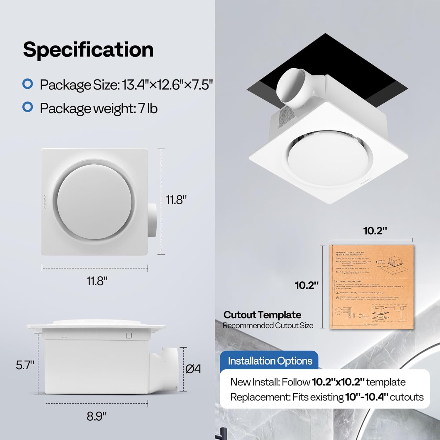
Figure 5: Product dimensions and mounting hole size.
5.2 Cutting the Mounting Hole
- Secure the provided cutout template to the ceiling with tape.
- Trace the outline with a pencil.
- Using a jab saw or appropriate cutting tool, carefully cut along the traced template edge for a clean cut. Double-check alignment to ensure the cut is within the template boundaries.

Figure 6: Visual guide for the 4-step installation process.
5.3 Ducting Connection
- Attach the flexible 4-inch duct hose to the exhaust fan unit's duct connector. Secure it firmly using the provided duct clamp.
- Connect the other end of the duct hose to your existing ventilation system, ensuring a tight and secure connection to prevent air leakage.
5.4 Electrical Wiring
- Connect the fan's electrical wires to your household wiring. This unit features a double insulation design and does not require a ground wire. Refer to the wiring diagram in the user manual for specific connections (typically black to live, white to neutral).
- Ensure all connections are secure using appropriate wire connectors.

Figure 7: Electrical connections, highlighting double insulation and no ground wire requirement.
5.5 Mounting the Fan Unit
- Lift the fan unit into the ceiling opening.
- Secure the fan housing to the ceiling joists or framing using the provided screws. The unit has multiple screw holes to accommodate various setups.
- Ensure the unit is firmly in place and flush with the ceiling surface.
5.6 Attaching the Grille
- Connect the light module cable to the driver unit inside the fan housing.
- Pinch the spring clips on the grille and insert them into the slots on the fan housing.
- Push the grille firmly until it snaps into place, ensuring it is flush with the ceiling.
Video 2: Installation process of the VIVOHOME AutoFlow Bathroom Exhaust Fan with Humidity Sensor.
6. Operating Instructions
Your VIVOHOME Autoflow Bathroom Exhaust Fan can be operated manually via the remote control or automatically using its intelligent humidity sensor.
6.1 Remote Control Functions
The included wireless remote control provides full command over the fan and light settings:
- ON/OFF Button: Powers the unit on or off.
- Fan Speed Control: Adjusts fan speed with 6 levels. Use '+' and '-' buttons to increase or decrease.
- Light Switch: Toggles the light on/off and cycles through color temperatures (2700K, 4000K, 5700K).
- Brightness Control: Adjusts light brightness with 6 levels. Use '+' and '-' buttons.
- Fixed Light Setting: One-touch access to 4000K Neutral White at 100% brightness (1500 Lumens).
- Night Mode: Activates 2700K Warm Light at 200 Lumens for a soft glow.
- Timer: Sets a 1-hour timer for operation.
- AUTO Button: Activates the Autoflow humidity-sensing mode.

Figure 8: Remote control layout and functions.
6.2 Autoflow Humidity-Sensing Mode
When the AUTO button is pressed, the fan will automatically adjust its speed based on the room's humidity level:
- Low Humidity (RH < 50%): Fan operates at 30 CFM for minimal energy consumption and continuous odor elimination.
- Moderate Humidity (50% < RH < 80%): Fan operates at 110 CFM for normal ventilation.
- High Humidity (RH > 80%): Fan operates at 160 CFM for powerful steam and odor removal.

Figure 9: Autoflow mode automatically adjusts fan speed based on humidity.
7. Maintenance
Regular maintenance ensures optimal performance and longevity of your exhaust fan.
7.1 Cleaning the Grille and Fan Blades
- Safety First: Turn off power at the circuit breaker before cleaning.
- Gently pull down the grille to release the spring clips and remove it from the housing.
- Wipe the grille with a soft, damp cloth. For stubborn dirt, use a mild detergent.
- Carefully clean the fan blades and interior of the housing with a soft brush or vacuum cleaner to remove dust and debris.
- Once clean and dry, reattach the grille by pinching the spring clips and pushing it back into the housing until it snaps into place.
7.2 Duct Inspection
Periodically inspect the ducting for any blockages, kinks, or damage that could impede airflow. Ensure all connections remain secure.
8. Troubleshooting
If you encounter issues with your VIVOHOME Autoflow Bathroom Exhaust Fan, refer to the following troubleshooting guide:
| Problem | Possible Cause | Solution |
|---|---|---|
| Fan does not turn on. | No power supply. | Check circuit breaker and wall switch. Ensure wires are correctly connected. |
| Fan is noisy. | Loose mounting screws or debris in fan blades. | Ensure fan is securely mounted. Clean fan blades and housing (refer to Maintenance section). |
| Poor ventilation. | Duct blockage or improper ducting. | Check ducting for obstructions or kinks. Ensure duct connections are sealed. |
| Light does not work. | Loose electrical connection or faulty LED module. | Check light module connection to the driver unit. If issue persists, contact support. |
| Autoflow mode not functioning. | Humidity sensor malfunction or incorrect setting. | Ensure AUTO mode is selected on the remote. If the issue persists, contact support. |
9. Specifications
| Feature | Specification |
|---|---|
| Brand | VIVOHOME |
| Model Name | VH1810 |
| Air Flow Capacity | 30-110-160 CFM (Cubic Feet Per Minute) |
| Noise Level | 0.1 - 1.5 Sones |
| Wattage | 45 Watts |
| Voltage | 110V-120V / 60Hz |
| Motor Type | Brushless EC Motor |
| Light Color Temperature | 2700K (Warm), 4000K (Neutral), 5700K (Cool White) |
| Light Brightness | Up to 1500 Lumens (4000K, 100% brightness) |
| Control Method | Remote Control |
| Product Dimensions | 11.8"D x 11.8"W x 6.7"H |
| Mounting Hole Size | 10.2" x 10.2" (New Install), Fits existing 10"-10.4" cutouts (Replacement) |
| Duct Size | Ø4-inch |
| Recommended Room Size | 86–129 sq ft |

Figure 10: Detailed installation parameters and dimensions.
10. Warranty and Support
For warranty information, technical support, or to inquire about replacement parts, please contact VIVOHOME customer service. Refer to the contact information provided on the product packaging or the official VIVOHOME website.
Note: Keep your purchase receipt as proof of purchase for warranty claims.