1. Introduction
This manual provides detailed instructions for the installation, operation, and maintenance of the Generic Desktop Motherboard LA-A061P. Please read this manual thoroughly before proceeding with installation to ensure proper setup and to prevent damage to the product or other components. This motherboard is designed for compatibility with systems such as C560, C540, C320, B4030, and B5030.
2. Safety Information
Observe the following safety precautions to prevent damage and ensure safe operation:
- Always disconnect the power supply from your computer before installing or removing any components.
- Wear an anti-static wrist strap or frequently touch a grounded metal object to discharge static electricity before handling the motherboard or other components. Static discharge can damage electronic components.
- Handle the motherboard by its edges to avoid touching sensitive components.
- Ensure proper ventilation within your computer case to prevent overheating.
- Keep the motherboard away from liquids and extreme temperatures.
3. Package Contents
Verify that all items are present in your package. If any items are missing or damaged, contact your vendor immediately.
- Generic Desktop Motherboard LA-A061P
- User Manual (this document)
- Driver CD/DVD (may be included, or drivers available online)
4. Product Overview
The Generic Desktop Motherboard LA-A061P is a replacement or upgrade component for compatible desktop systems. It features various ports and slots for essential computer components.

Figure 4.1: Overview of the Generic Desktop Motherboard LA-A061P. This image displays the entire motherboard, highlighting the CPU socket, RAM slots, various expansion slots, and I/O ports.
Key components include:
- CPU Socket: The central processing unit (CPU) is installed here.
- RAM Slots: For installing DDR3 or DDR4 memory modules (check specific model for compatibility).
- PCIe Slots: For graphics cards and other expansion cards.
- SATA Ports: For connecting storage devices like HDDs and SSDs.
- I/O Panel: Includes USB ports, Ethernet port, audio jacks, and video outputs (VGA, HDMI, DisplayPort, depending on model).

Figure 4.2: Close-up view of the motherboard's model identification label. This label clearly shows 'LA-A061P', confirming the specific model of the motherboard.
5. Setup and Installation
Follow these steps carefully to install your new motherboard.
5.1 Preparation
- Ensure your computer is powered off and unplugged from the wall outlet.
- Open your computer case and remove any existing motherboard if you are replacing one.
- Place the new motherboard on an anti-static mat or in its anti-static bag on a flat, stable surface.
5.2 CPU Installation
- Locate the CPU socket on the motherboard.
- Gently lift the load lever and open the CPU socket cover.
- Align the CPU with the socket, matching the golden triangle or notch on the CPU with the corresponding mark on the socket. Do not force the CPU into place.
- Lower the CPU into the socket.
- Close the socket cover and push down the load lever until it clicks into place.
- Apply thermal paste to the top of the CPU and install the CPU cooler according to its instructions.
5.3 RAM Installation
- Locate the RAM slots.
- Open the clips at both ends of the RAM slot.
- Align the notch on the RAM module with the notch in the slot.
- Press down firmly on both ends of the RAM module until the clips snap into place.
5.4 Connecting Peripherals and Power
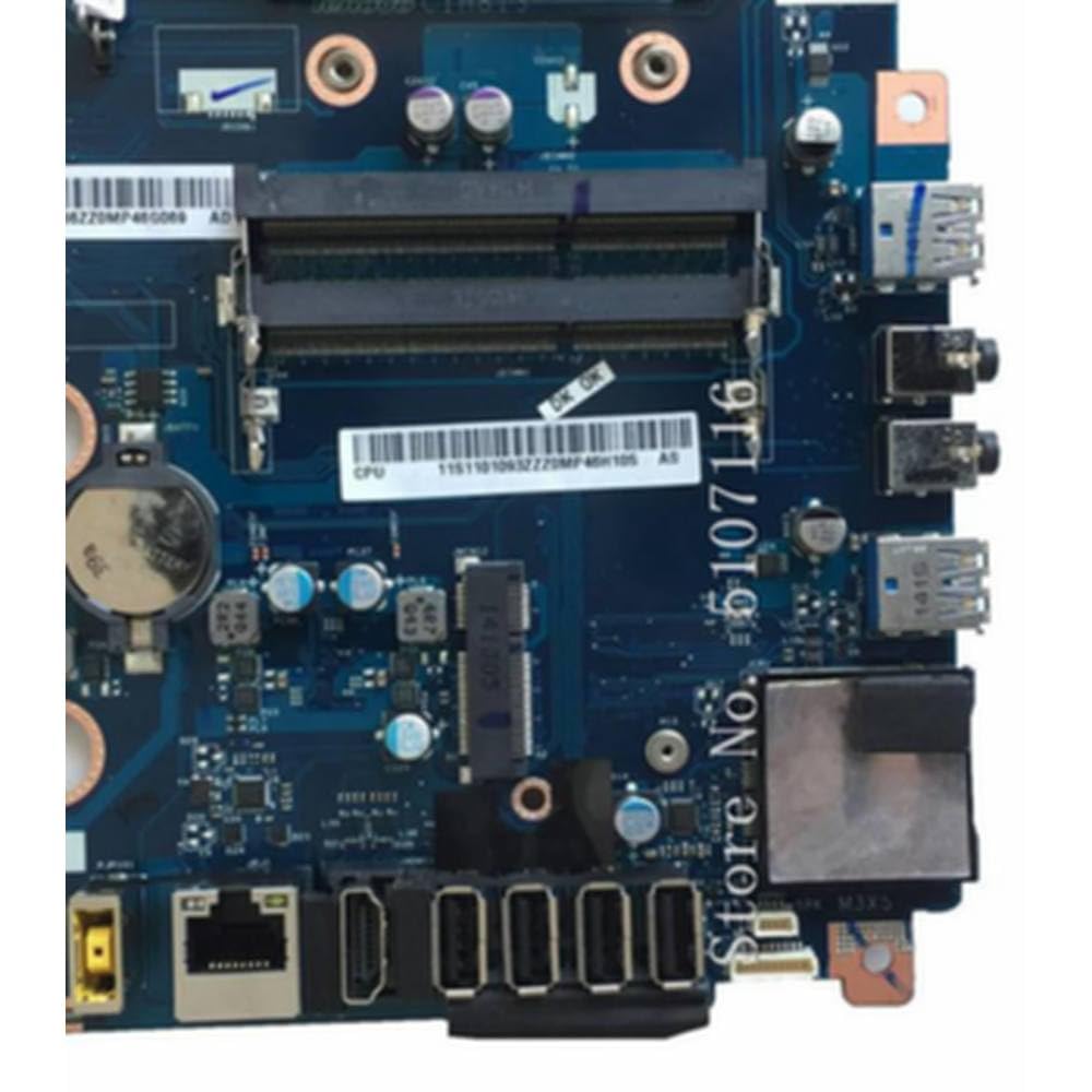
Figure 5.1: Detailed view of the motherboard's I/O panel and CPU socket area. This image shows the various external ports (USB, Ethernet, audio) and the CPU socket with RAM slots nearby, crucial for connecting components.
- Power Connectors: Connect the 24-pin ATX power connector and the 4-pin or 8-pin CPU power connector from your power supply to the motherboard.
- SATA Devices: Connect your storage drives (HDD/SSD) to the SATA ports using SATA data cables. Connect power from the PSU to these drives.
- Front Panel Connectors: Connect the power button, reset button, HDD LED, power LED, and front panel USB/audio connectors from your case to the corresponding headers on the motherboard. Refer to your case manual for specific pin assignments.
- Expansion Cards: Install any graphics cards or other PCIe expansion cards into the appropriate slots.
5.5 Mounting the Motherboard
- Carefully place the motherboard into your computer case, aligning the screw holes with the standoffs.
- Secure the motherboard with screws. Do not overtighten.
- Ensure the I/O shield is properly seated in the case opening and aligns with the motherboard's I/O ports.
6. Operating Instructions
6.1 First Boot
- After all components are installed and connected, close your computer case.
- Connect your monitor, keyboard, mouse, and power cable.
- Turn on the power supply and press the power button on your computer case.
- The system should power on and display the BIOS/UEFI screen or begin booting into your operating system.
6.2 Accessing BIOS/UEFI
To access the BIOS/UEFI setup utility, press the designated key (commonly DEL, F2, F10, or F12) repeatedly during the initial boot sequence. The exact key may vary; refer to the on-screen prompts during startup.
7. Maintenance
7.1 Cleaning
- Regularly clean dust from inside your computer case using compressed air.
- Ensure the computer is powered off and unplugged before cleaning.
- Avoid using liquid cleaners directly on components.
7.2 BIOS/UEFI Updates
Periodically check the manufacturer's website (if available) for BIOS/UEFI updates. Updates can improve system stability, add support for new hardware, or fix bugs. Follow the update instructions provided by the manufacturer carefully to avoid damaging the motherboard.
8. Troubleshooting
If you encounter issues, refer to the following common troubleshooting steps:
- No Power: Ensure all power cables (24-pin ATX, 4/8-pin CPU) are securely connected. Check the power supply unit (PSU) switch and wall outlet.
- No Display: Verify that the monitor is connected to the correct video output (either integrated graphics or a dedicated graphics card). Reseat the graphics card and RAM modules.
- System Fails to Boot: Check all component connections. Try booting with only essential components (CPU, one RAM stick, graphics card if no integrated graphics). Listen for beep codes, which can indicate specific errors.
- Peripherals Not Detected: Ensure USB devices are connected to working ports. Check drivers for specific devices.
- Overheating: Ensure CPU cooler is properly installed and fans are spinning. Check for adequate airflow in the case.
9. Specifications
| Feature | Description |
|---|---|
| Model Number | LA-A061P, CIH81S |
| Compatibility | C560, C540, C320, B4030, B5030 Desktop Systems |
| Manufacturer | Generic |
| ASIN | B0FGKJPH7 |
| Date First Available | July 3, 2025 |
10. Warranty and Support
This product is manufactured by Generic. For specific warranty terms and technical support, please refer to the documentation provided with your purchase or contact your retailer. Keep your proof of purchase for warranty claims.


