
1. Introduction
This instruction manual provides detailed guidance for assembling, operating, and maintaining your LOMEDRETME RDA5807 Audio Module FM Radio Kit. This DIY kit is designed for electronic production training and hobbyists interested in building their own FM radio receiver. It features the RDA5807 FM radio module, offering a frequency range of 76-108MHz and operating on a low voltage of 1.8-3.6V. Please read this manual thoroughly before beginning assembly to ensure proper function and safety.
2. Safety Information
- Soldering Safety: Always use a soldering iron in a well-ventilated area. Avoid touching the hot tip of the soldering iron. Wear safety glasses to protect your eyes from solder splashes.
- Electrical Safety: Ensure the power supply voltage (1.8-3.6V) is correctly applied. Incorrect voltage can damage components. Do not short-circuit the battery terminals.
- Component Handling: Some electronic components can be sensitive to electrostatic discharge (ESD). Handle components by their edges and consider using an anti-static mat or wrist strap.
- Small Parts: This kit contains small parts that could be a choking hazard. Keep out of reach of small children.
3. Package Contents
Please verify that all components listed below are present in your kit before starting assembly.
- RDA5807 FM Radio Module (often pre-assembled on a small board)
- Main Printed Circuit Board (PCB)
- Battery Holder (typically for AA batteries)
- Various Electronic Components: Resistors, Capacitors, Diodes, Transistors, Integrated Circuits (ICs), Buttons, Audio Jack, Power Switch, LEDs, etc.
- Connecting Wires
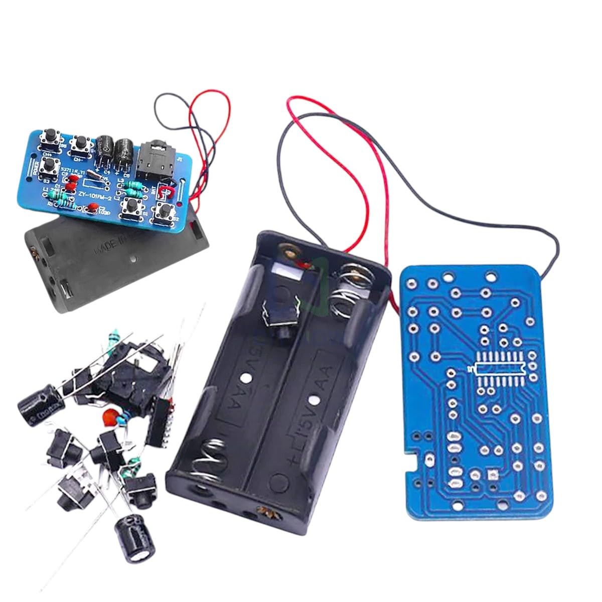
Figure 3.1: Overview of the LOMEDRETME RDA5807 FM Radio Kit components, including the main PCB, battery holder, pre-assembled module, and various loose electronic parts.

Figure 3.2: An assortment of common electronic components such as resistors, capacitors, and integrated circuits, similar to those found in the kit.
4. Product Overview
The LOMEDRETME RDA5807 Audio Module FM Radio Kit allows users to construct a functional FM radio receiver. The core of the kit is the RDA5807 module, which integrates a complete FM tuner, allowing for high-quality radio reception. This kit is an excellent educational tool for understanding basic electronics, soldering techniques, and radio frequency principles.
- Frequency Range: 76-108MHz (worldwide FM band)
- Operating Voltage: 1.8V to 3.6V DC
- Low Power Consumption: Designed for efficient battery operation.
- Audio Output: Typically via a 3.5mm headphone jack.
- Control Interface: Usually button-based for tuning and volume.

Figure 4.1: An isometric representation of various semiconductor and electronic components, illustrating the diversity of parts that may be included in such a DIY kit.
5. Setup Instructions (Assembly)
This section guides you through the assembly process. A soldering iron, solder, wire cutters, and a multimeter are recommended tools.
- Prepare Your Workspace: Ensure a clean, well-lit, and well-ventilated area. Gather all components and tools.
- Identify Components: Match each component from your kit to the corresponding labels or silkscreen markings on the main PCB. Pay attention to resistor values (color codes), capacitor polarities, and IC orientations.
- Solder Smallest Components First: Begin by soldering the smallest components, such as resistors and diodes, onto the PCB. Insert the component, bend the leads slightly to hold it in place, and then solder each lead from the underside of the board. Trim excess leads.
- Solder Capacitors and Transistors: Proceed with capacitors (observing polarity for electrolytic capacitors), transistors, and other medium-sized components.
- Solder Integrated Circuits (ICs) and Sockets: If your kit includes IC sockets, solder them first. Then carefully insert the ICs into their sockets, ensuring correct orientation (usually indicated by a notch or dot). If soldering ICs directly, align them correctly before soldering.
- Solder Connectors and Switches: Attach the audio jack, power switch, and any other connectors or buttons.
- Connect Battery Holder: Solder the wires from the battery holder to the designated power input points on the PCB (usually marked + and - or VCC and GND). Ensure correct polarity.
- Integrate RDA5807 Module: If the RDA5807 is on a separate small module, carefully solder its pins to the corresponding header on the main PCB.
- Visual Inspection: After all components are soldered, carefully inspect the PCB for any cold solder joints, solder bridges (short circuits between pads), or incorrectly oriented components.
6. Operating Instructions
Once assembled, follow these steps to operate your FM radio kit.
- Insert Batteries: Open the battery holder and insert the required AA batteries, observing the correct polarity (+/-).
- Connect Antenna: Ensure a suitable antenna (often a simple wire) is connected to the designated antenna terminal on the PCB.
- Connect Headphones/Speakers: Plug your 3.5mm headphones or external speakers into the audio output jack.
- Power On: Flip the power switch to the 'ON' position. An indicator LED may light up.
- Tune Stations: Use the designated buttons (e.g., 'UP'/'DOWN' or 'SCAN') to tune to FM radio stations. Some kits may have an auto-scan feature.
- Adjust Volume: Use the volume control buttons or potentiometer to set the desired audio level.
- Power Off: When finished, flip the power switch to the 'OFF' position to conserve battery life.
7. Maintenance
Proper maintenance ensures the longevity and optimal performance of your kit.
- Battery Replacement: Replace batteries when audio quality degrades or the device fails to power on. Always use fresh batteries of the correct type.
- Cleaning: Use a soft, dry cloth to clean the exterior of the assembled kit. Avoid using liquids or abrasive cleaners. For dust on the PCB, use compressed air or a soft brush.
- Storage: Store the kit in a cool, dry place away from direct sunlight and extreme temperatures. If storing for extended periods, remove the batteries to prevent leakage.
- Component Check: Periodically inspect solder joints for cracks or corrosion, especially if the device is handled frequently.
8. Troubleshooting
If you encounter issues, refer to the following troubleshooting guide.
| Problem | Possible Cause | Solution |
|---|---|---|
| No power / Device does not turn on |
|
|
| No sound or very low sound |
|
|
| Poor FM reception / Static |
|
|
| Components get hot |
|
|
9. Specifications
- Model: RDA5807
- Brand: LOMEDRETME
- Frequency Range: 76-108MHz
- Operating Voltage: 1.8V - 3.6V DC
- Power Supply: Typically 2x AA batteries (not included)
- Audio Output: 3.5mm stereo jack
- ASIN: B0FGH5NYDX
- Date First Available: July 2, 2025
10. Warranty and Support
LOMEDRETME is committed to providing quality electronic products and customer satisfaction. While this is a DIY kit, we offer support for manufacturing defects in the components provided. If you encounter any issues with defective components or require assistance with assembly, please contact our customer support team.
- Money-Back Guarantee: We stand by the quality of our products. If you are not satisfied, please refer to the retailer's return policy for details on our money-back guarantee.
- Customer Support: Our knowledgeable team is available to answer any questions or concerns you may have regarding your LOMEDRETME RDA5807 Audio Module FM Radio Kit. Please reach out through the platform where you purchased the product.