1. Introduction
This manual provides essential information for the safe and efficient operation of your Kemot PROavr-10k Automatic Three-Phase Voltage Stabilizer. Please read these instructions carefully before installation and use. This device is designed to protect your electronic equipment from voltage fluctuations, ensuring a stable power supply.
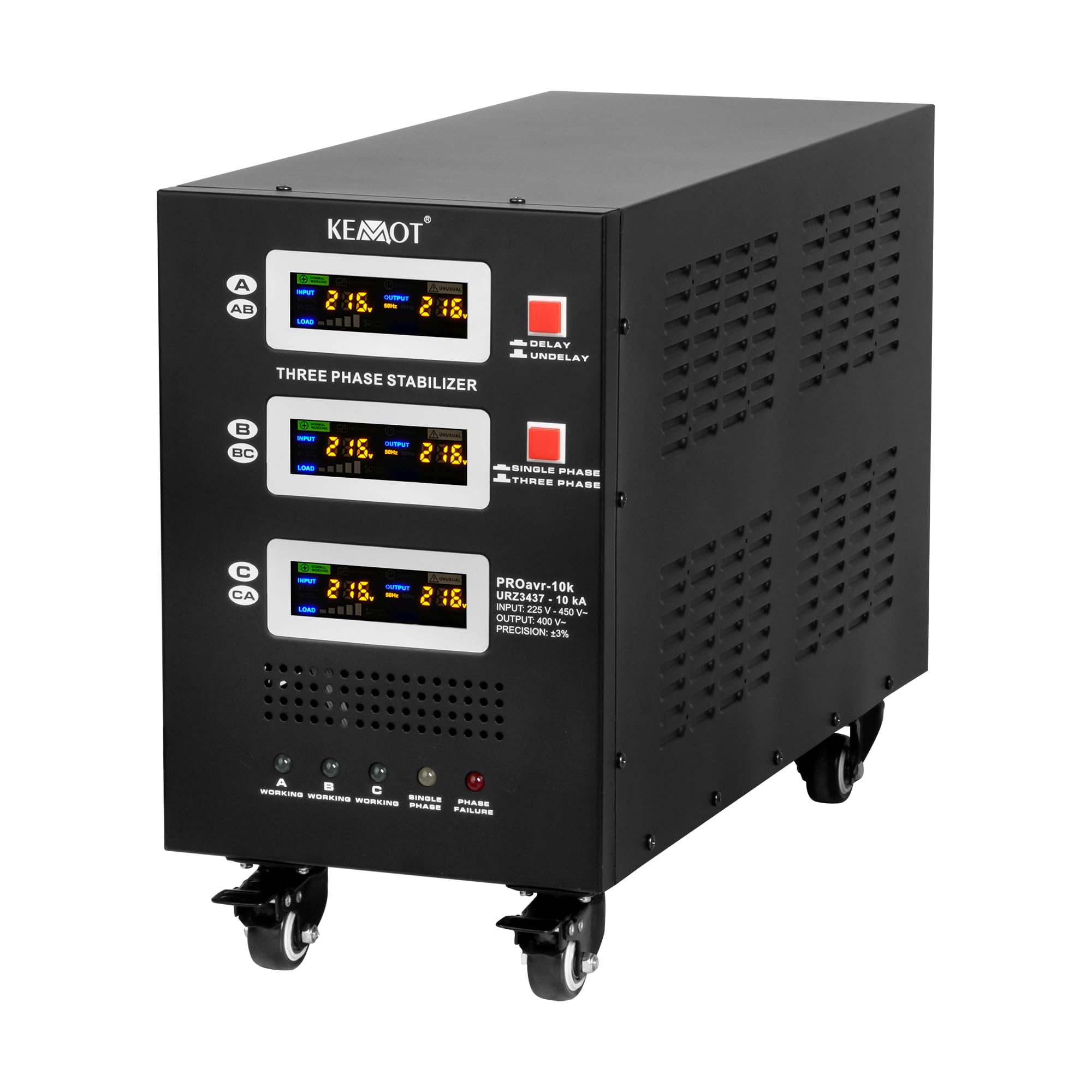
Figure 1: Kemot PROavr-10k Automatic Three-Phase Voltage Stabilizer. This image shows the overall design of the stabilizer, featuring its robust casing and integrated wheels for mobility.
2. Safety Instructions
- Ensure the stabilizer is placed on a stable, level surface with adequate ventilation.
- Do not operate the device in humid or dusty environments.
- Before connecting or disconnecting any cables, ensure the stabilizer is turned off and disconnected from the main power supply.
- All electrical connections must be performed by a qualified electrician in accordance with local electrical codes.
- Do not open the casing of the stabilizer. There are no user-serviceable parts inside. Refer all servicing to qualified personnel.
- Keep children and pets away from the device during operation.
3. Product Features
- Reliable Device Protection: The KEMOT PROavr-10k stabilizer effectively protects against voltage surges and drops, ensuring safe and stable operation of electronic devices.
- Single and Three-Phase Operation: Adaptable for both single-phase and three-phase operation, providing precise voltage control for a wide range of equipment.
- Precise Voltage Regulation: Thanks to its servo motor mechanism, it maintains voltage with an accuracy of ±3%, guaranteeing stability even with significant input voltage fluctuations.
- Bypass Function and Delay: Equipped with a BYPASS function and a DELAY start-up delay from 6 to 180 seconds, protecting connected devices from overloads.
- Easy Transport: The stabilizer is equipped with sturdy wheels, allowing for easy movement and positioning in a convenient location.

Figure 2: Application diagram. This illustration demonstrates how the voltage stabilizer can protect multiple electronic devices in a home or office environment.
4. Setup
- Unpacking: Carefully remove the stabilizer from its packaging. Inspect for any signs of damage during transit.
- Placement: Position the stabilizer in a well-ventilated area, away from direct sunlight, heat sources, and moisture. The integrated wheels (Figure 3) facilitate easy movement.
- Electrical Connections:
- Identify the AC INPUT and AC OUTPUT terminals on the rear panel (Figure 4).
- Connect the three-phase main power supply to the AC INPUT terminals (A, B, C, N, GND).
- Connect your protected equipment to the AC OUTPUT terminals (A, B, C, N, GND).
- Ensure all connections are secure and correctly phased.
- Circuit Breakers: Verify that all circuit breakers (A, B, C) on the rear panel are in the 'OFF' position before connecting to the main power.

Figure 3: Stabilizer wheels. The robust wheels allow for easy relocation of the unit.

Figure 4: Rear panel connections. This view highlights the input and output terminals, along with individual phase power switches and circuit breakers.
5. Operating Instructions
- Power On: After all connections are made, switch on the main power supply to the stabilizer. Then, turn on the individual phase power switches (A, B, C) on the rear panel.
- Monitoring: The front LCD display (Figure 5) will show input voltage, output voltage, and load percentage for each phase (A, B, C).
- Delay Function: The stabilizer features a selectable start-up delay (6 or 180 seconds) to protect connected devices from immediate power surges after a power outage. This is indicated by the 'DELAY' and 'UNDELAY' indicators.
- Bypass Mode: The 'BYPASS' switch allows you to bypass the stabilization function, directly supplying power from the input to the output. Use this only when stable input voltage is guaranteed.
- Indicators:
- Working (A, B, C): Green lights indicate normal operation for each phase.
- Single Phase: Yellow light indicates operation in single-phase mode.
- Phase Failure: Red light indicates a phase failure, requiring immediate attention.
- Power Off: To turn off the stabilizer, first switch off the individual phase power switches (A, B, C) on the rear panel, then disconnect the main power supply.

Figure 5: Front panel display and controls. This image details the user interface for monitoring and controlling the stabilizer's operation.
6. Maintenance
- Cleaning: Regularly clean the exterior of the stabilizer with a soft, dry cloth. Do not use liquid cleaners or solvents.
- Ventilation: Ensure that the ventilation openings on the sides and rear of the unit are clear of obstructions to prevent overheating.
- Inspection: Periodically check all cables and connections for signs of wear or damage. Replace any damaged cables immediately.
- Cooling System: The cooling fan activates when the load reaches 30% of the rated power and deactivates when the load drops below 20%. Ensure the fan operates freely.
7. Troubleshooting
If you encounter issues with your stabilizer, refer to the following common problems and solutions:
| Problem | Possible Cause | Solution |
|---|---|---|
| No power to connected devices | Stabilizer is off, circuit breaker tripped, or input power failure. | Check power switches, reset circuit breakers, verify main power supply. |
| Output voltage unstable | Input voltage outside stabilization range, or overload. | Check input voltage. Reduce connected load. Refer to specifications for operating range. |
| Overload warning/shutdown | Total power of connected devices exceeds stabilizer's capacity. | Disconnect some devices to reduce the load. Restart the stabilizer. |
| Overheating | Poor ventilation or excessive load. | Ensure adequate airflow around the unit. Reduce load. Allow unit to cool down. |
| Phase Failure indicator is on | One or more input phases are missing or unstable. | Check the three-phase input power supply. Consult a qualified electrician. |

Figure 6: AVR operation curve. This graph demonstrates the stabilizer's ability to correct input voltage fluctuations to maintain a stable output.
8. Specifications
| Parameter | Value |
|---|---|
| Rated Power | 10000 VA / 10000 W |
| Input Voltage Range | 225 - 450 V |
| Minimum Startup Voltage | 225 V |
| Output Voltage Range | 400 V |
| Phases | 1 / 3 phases |
| Stabilization Precision | ± 3% |
| Efficiency | 98% |
| Stabilization Control | Servo Motor |
| Transformer Type | C.R.G.O. Toroidal |
| Display | LCD |
| Operating Frequency | 50 / 60 Hz |
| Start Delay Switch | 6 / 180 s |
| Housing Material | Steel |
| Operating Temperature | 0 – 40°C |
| Relative Humidity | 10 – 102% |
| Storage Temperature | -15°C – 45°C |
| Protections | Overload, Short Circuit, High/Low Voltage, Overheating |
| Cooling Activation | At 30% of rated power |
| Cooling Deactivation | At 20% of rated power |
| Dimensions (L x W x H) | 545 x 230 x 397 mm (54.5 x 23 x 39.7 cm) |
| Weight | 31 kg |
| Model Number | URZ3437 |
9. Warranty and Support
This Kemot PROavr-10k Voltage Stabilizer comes with a 2-year manufacturer's warranty. Please retain your proof of purchase for warranty claims.
For technical support, service, or warranty inquiries, please contact your retailer or the manufacturer directly. Provide the model number (URZ3437) and a detailed description of the issue when seeking assistance.


