Introduction
This manual provides detailed instructions for the installation, operation, and maintenance of your Ylwxzenith 30A Electric Bike Controller Kit with UKC1 LCD Panel. This kit is designed to convert standard bicycles into electric vehicles, compatible with 750W-1000W motors and 24V, 36V, or 48V systems. Please read this manual thoroughly before installation and use to ensure proper function and safety.
Safety Information
- Always wear appropriate safety gear, including a helmet, when operating an electric bicycle.
- Ensure all connections are secure and properly insulated to prevent short circuits.
- Do not attempt to modify the controller or LCD panel. Unauthorized modifications can lead to malfunction and void the warranty.
- Keep the controller and display away from water and extreme temperatures. While the housing offers protection, it is not fully submersible.
- Before performing any maintenance or adjustments, ensure the electric bicycle is powered off and the battery is disconnected.
- Consult a qualified technician if you are unsure about any installation or troubleshooting steps.
Package Contents
Verify that all items listed below are present in your package:
- 1 x 30A Electric Bike Controller
- 1 x UKC1 LCD Panel with integrated control buttons
- 4 x Washers
- 3 x Screws
- 3 x Nuts
- 1 x Instruction Manual (this document)
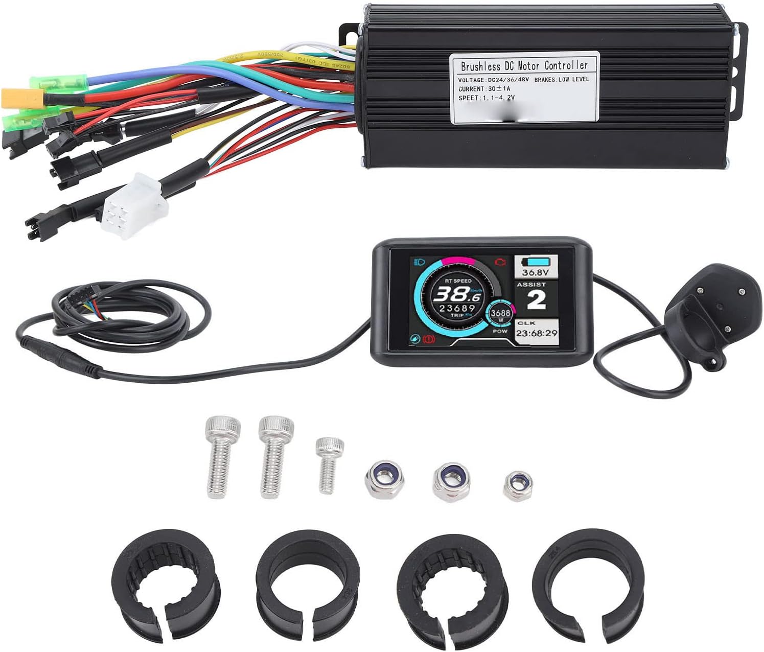
Figure 1: Overview of the Ylwxzenith 30A Electric Bike Controller Kit, showing the controller, UKC1 LCD panel, wiring, and mounting hardware.
Setup and Installation
Follow these steps carefully to install your electric bike controller kit.
1. Controller Mounting
- Identify a suitable location on your bicycle frame for the controller. Ensure it is protected from direct impact and excessive moisture.
- Use the provided screws and nuts to securely mount the controller. The aluminum alloy housing is designed for heat dissipation, so ensure adequate airflow around it.

Figure 2: Controller dimensions: approximately 150mm (5.9in) length, 60mm (2.4in) width, and 35mm (1.4in) height. These dimensions help in selecting a suitable mounting location.
2. LCD Panel Installation
- Attach the UKC1 LCD panel to your handlebar using the provided clamps and washers. Position it for optimal visibility and easy access to the control buttons.
- Ensure the panel is securely fastened and does not obstruct steering or braking.

Figure 3: Close-up view of the UKC1 LCD panel's control buttons, typically including Power, Mode, and Up/Down arrows for settings adjustment.
3. Wiring Connections
The controller features various color-coded wires for different functions. Connect them according to your motor and battery system. Refer to the diagram below for general guidance. If you are unsure, consult a professional.
- Motor Wires: Connect the thick phase wires (usually green, blue, yellow) from the controller to the corresponding motor phase wires. Connect the thinner Hall sensor wires.
- Battery Wires: Connect the thick red wire from the controller to the positive (+) terminal of your battery and the thick black wire to the negative (-) terminal.
- LCD Panel Wire: Connect the multi-pin connector from the LCD panel to the corresponding port on the controller.
- Brake Levers: Connect the brake lever wires to the controller. These typically provide a low-level input to cut motor power when brakes are applied.
- Throttle: Connect the throttle wire to the controller.
- Pedal Assist Sensor (PAS): Connect the PAS sensor wire if your system includes one.

Figure 4: The electric bike controller and UKC1 LCD panel with all associated wiring. This image illustrates the various connectors extending from the controller, ready for connection to the motor, battery, and other components.
After all connections are made, secure any loose wiring with zip ties or cable wraps to prevent interference with moving parts.
Operating Instructions
1. Power On/Off
- To power on the system, press and hold the power button on the UKC1 LCD panel for a few seconds. The display will illuminate.
- To power off, press and hold the power button again until the display turns off.
2. LCD Display Functions
The UKC1 LCD panel provides real-time information about your electric bicycle's status:
- Battery Level: Indicates the remaining battery charge.
- Speed: Displays current riding speed.
- Assist Level/Mode: Shows the current pedal assist level (e.g., 1-3 or 1-5, depending on configuration).
- Trip Distance: Records the distance traveled for the current ride.
- Odometer: Displays total distance traveled.
- Error Codes: May display codes if a system error occurs. Refer to the Troubleshooting section.

Figure 5: The UKC1 LCD panel in operation, showing digital readouts for speed, battery voltage, assist level, trip distance, and power output. The display is backlit for visibility in various lighting conditions.
3. Adjusting Assist Levels
Use the '+' and '-' buttons on the LCD panel to cycle through the available pedal assist levels. Higher levels provide more motor assistance.
4. Throttle Operation (if applicable)
If a throttle is installed, gently twist or press it to engage motor power independently of pedaling. Always use the throttle responsibly and be aware of your surroundings.
Maintenance
- Cleaning: Wipe the controller and LCD panel with a soft, damp cloth. Do not use harsh chemicals or abrasive cleaners. Ensure no water enters the electrical components.
- Connection Check: Periodically inspect all wiring connections for signs of wear, corrosion, or looseness. Re-secure or replace as necessary.
- Physical Inspection: Check the controller housing and LCD panel for any physical damage. The aluminum alloy housing is designed for durability and heat dissipation.
- Storage: When not in use for extended periods, store the electric bicycle in a dry, temperate environment.
Troubleshooting
This section addresses common issues you might encounter. For problems not listed here, please contact customer support.
| Problem | Possible Cause | Solution |
|---|---|---|
| System does not power on. | Battery disconnected or low charge; loose power connection; faulty LCD panel. | Check battery connection and charge level. Ensure all power wires are securely connected. Test with a known good battery if possible. |
| Motor not assisting. | Loose motor connections; brake levers engaged; low assist level; faulty motor or controller. | Verify motor phase and Hall sensor connections. Ensure brake levers are not stuck. Increase assist level on the LCD. Check for error codes on the display. |
| Inaccurate speed reading. | Speed sensor misalignment or damage; incorrect wheel size setting in LCD. | Check speed sensor position and ensure it is clean. Consult LCD manual for adjusting wheel size settings. |
| LCD display shows error code. | Specific system malfunction. | Refer to the UKC1 LCD panel's specific error code list (if available in its dedicated manual) or contact support with the error code. |
Specifications
| Feature | Detail |
|---|---|
| Product Material | ABS, Rubber, Aluminum Alloy, Metal |
| Application | Suitable for 750W-1000W Motors |
| Controller Size | Approx. 150x60x35mm (5.9x2.4x1.4in) |
| Maximum Controller Current | 30 ±1A |
| Controller Voltage | DC24V, 36V, 48V (Auto-sensing) |
| Controller Speed Setting | 1.1-4.2V |
| Brake Input | Low Level |
| Weight (Kit) | Approx. 800g (28.2oz) |
| Model Name | Ylwxzenith9et2fg41as |
| Brand | Ylwxzenith |
Warranty Information
This Ylwxzenith product is covered by a manufacturer's warranty for 90 days from the date of purchase. The warranty covers defects in materials and workmanship under normal use. It does not cover damage resulting from misuse, accidents, unauthorized modifications, or improper installation.
Please retain your proof of purchase for warranty claims.
Customer Support
If you have any questions, require technical assistance, or need to make a warranty claim, please contact the seller or Ylwxzenith customer service through the platform where you purchased the product. Provide your model number (Ylwxzenith9et2fg41as) and a detailed description of the issue for faster service.
For additional resources, you may visit the Ylwxzenith brand page or product listing on the retailer's website.