JRAHK CON008B-6G kit-WXGN200
JRAHK 36V-60V 20A Brushless DC Motor Controller with LCD Display Kit
Model: CON008B-6G kit-WXGN200
1. Product Overview
The JRAHK 36V-60V 20A Brushless DC Motor Controller with LCD Display Kit is designed to enhance the performance and control of 250W-400W e-bikes and scooters. This comprehensive system provides precise power management, real-time operational data, and quiet motor operation through its advanced sine wave technology. The kit includes a high-efficiency controller and a user-friendly LCD display for easy monitoring and parameter adjustment.
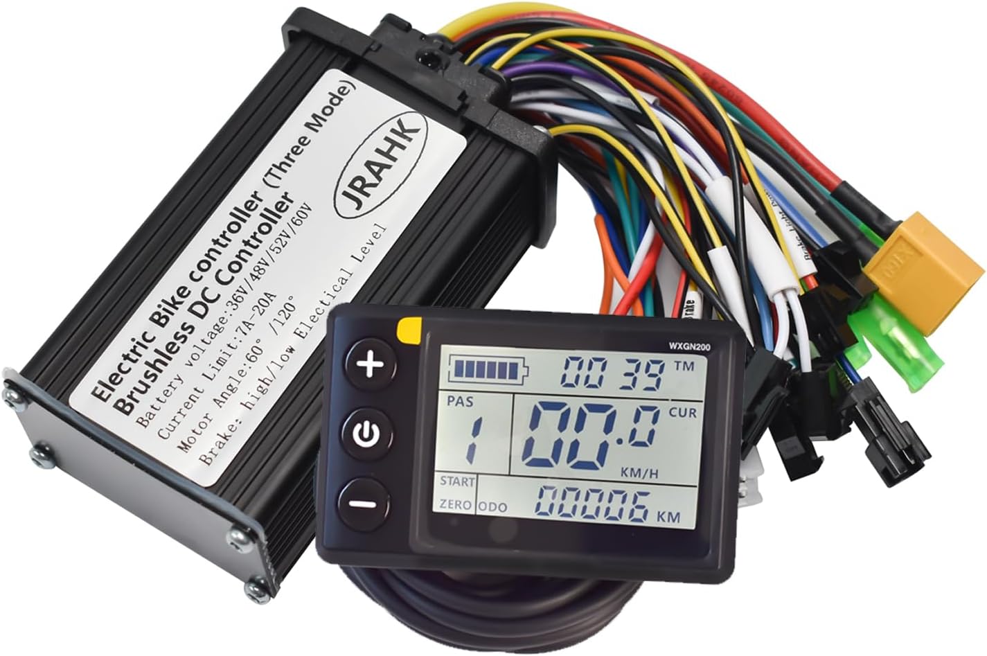
Image 1: The JRAHK Brushless DC Motor Controller and LCD Display Kit, showing the controller unit and the LCD screen with its cable.
2. What's in the Box
Upon opening the package, verify that all components are present and undamaged:
- High-efficiency Sine Wave Controller (approx. 90x56x32mm)
- LCD Display with Backlight
- LCD waterproof connector
- Wiring Instructions / Step-by-Step Installation Guide

Image 2: The product package on a digital scale, indicating a total weight of 367 grams.
3. Specifications
| Parameter | Specification |
|---|---|
| Brand | JRAHK |
| Model Number | CON008B-6G kit-WXGN200 |
| Voltage Range | 36V, 48V, 52V, 60V (Auto-Detect) |
| Max Current | 20A (Peak) |
| Output Modes | Sine Wave (Default) / Square Wave |
| Brake Compatibility | High-Level & Low-Level Signals |
| Motor Angle | 60° / 120° |
| Power Compatibility | 250W-400W Motors |
| Controller Dimensions | 90mm x 56mm x 32mm |
| Material | Aluminum (Controller Casing) |
| Item Weight | Approximately 13 ounces (0.81 lbs) |
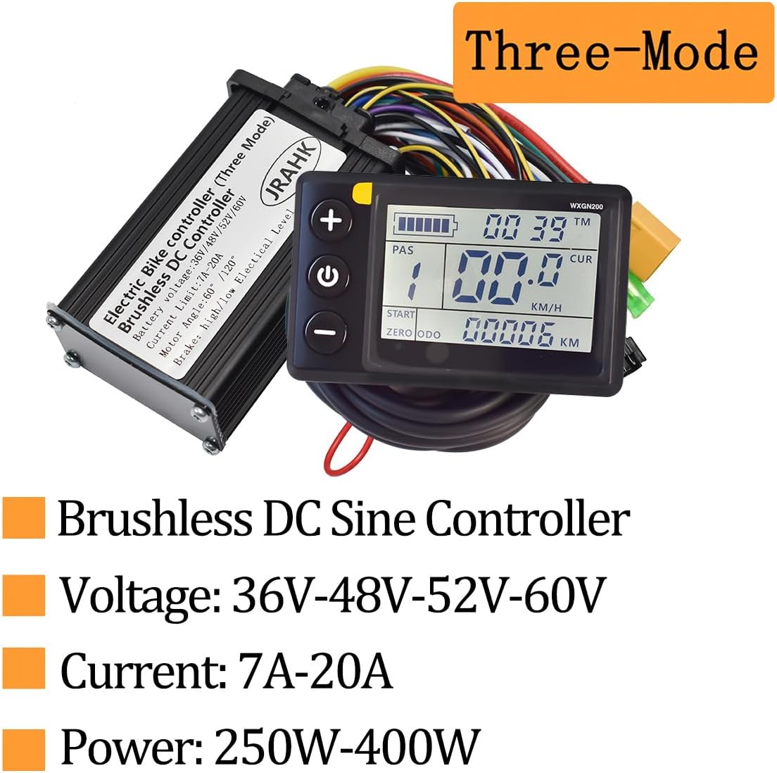
Image 3: Key specifications highlighted, including Brushless DC Sine Controller, Voltage (36V-48V-52V-60V), Current (7A-20A), and Power (250W-400W).

Image 4: Diagram illustrating the maximum dimensions of the controller: 90mm length, 56mm width, and 32mm height.
4. Setup & Installation Guide
This kit is designed for straightforward installation. Follow these general steps for connecting the controller and display to your e-bike or scooter system. It is recommended to disconnect the battery before beginning installation.
4.1. Wiring Connections
Refer to the detailed wiring diagram below for proper connection of all components. Ensure all connectors are securely fastened.
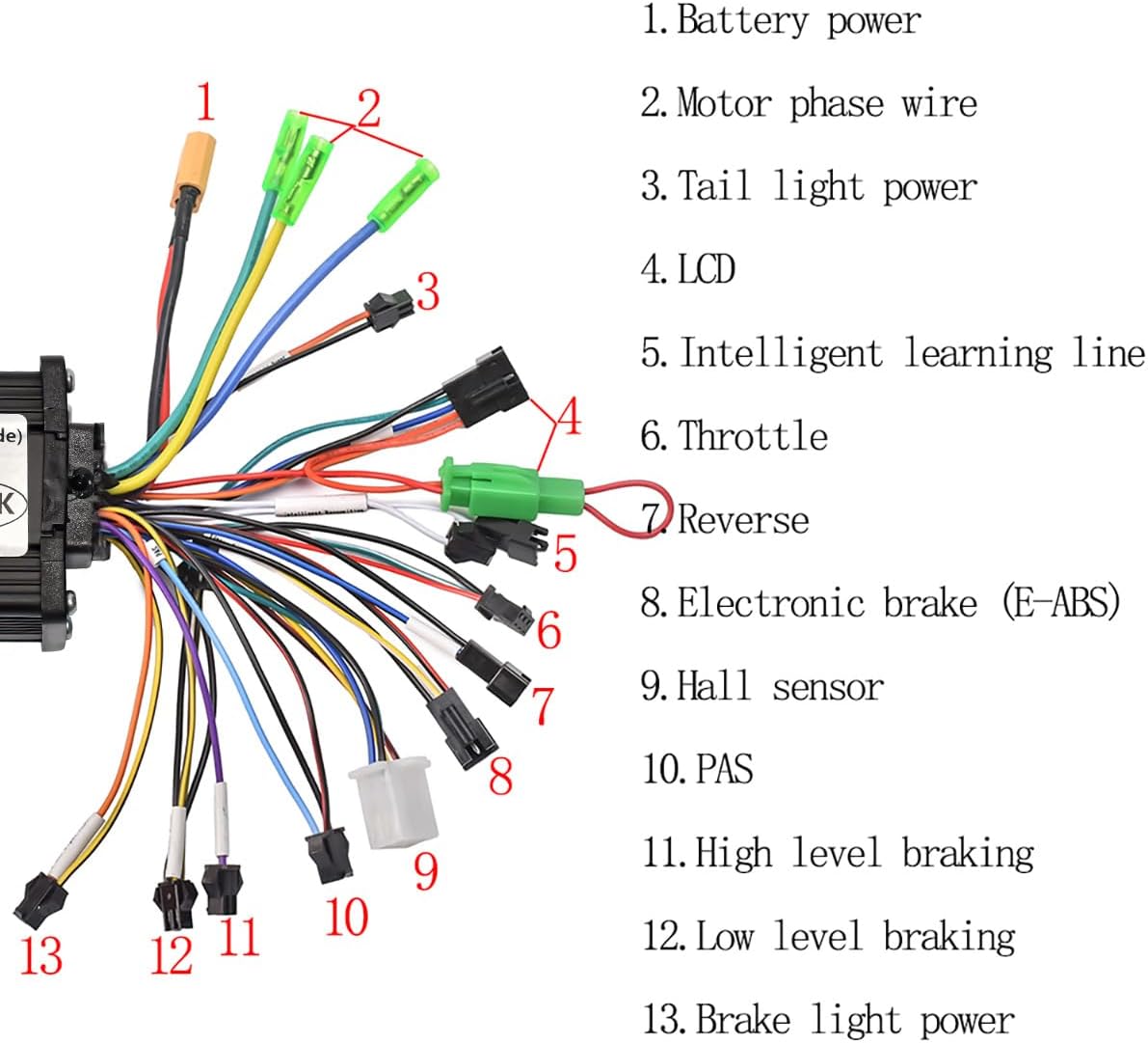
Image 5: Detailed wiring diagram showing numbered connections for the controller. Each number corresponds to a specific component or function.
- Battery Power: Connect to your e-bike's battery output.
- Motor Phase Wire: Connect to the motor's phase wires (typically three thick wires).
- Tail Light Power: Optional connection for a tail light.
- LCD: Connect the LCD display unit via its waterproof connector.
- Intelligent Learning Line: Used for motor direction self-learning (see 4.2).
- Throttle: Connect to the throttle control.
- Reverse: Optional connection for reverse function (if applicable).
- Electronic Brake (E-ABS): Connect to the electronic brake lever.
- Hall Sensor: Connect to the motor's Hall sensor wires (typically five thinner wires).
- PAS (Pedal Assist System): Connect to the PAS sensor.
- High Level Braking: Connect to high-level brake signal.
- Low Level Braking: Connect to low-level brake signal.
- Brake Light Power: Optional connection for a brake light.

Image 6: Illustration showing how the controller connects to a headlight, indicating a typical accessory connection point.
4.2. Motor Direction Self-Learning (One-Click Setup)
The controller features an auto-learning function for motor phase and Hall wires, simplifying setup:
- Ensure all other connections are made (battery, motor, throttle, display).
- Connect the "Intelligent Learning Line" (connection #5 in the diagram).
- Power on the system. The motor will automatically rotate.
- If the motor rotates in the correct direction, disconnect the "Intelligent Learning Line" after a few seconds. The learning process is complete.
- If the motor rotates in the wrong direction, disconnect the "Intelligent Learning Line", then reconnect it immediately. The motor will reverse direction. Once it rotates correctly, disconnect the line.
4.3. PAS Sensor Recommendation
For optimal pedal assist functionality, the JRAHK official store recommends using a single Hall PAS sensor, specifically a 6-magnet 12-signal universal PAS. This type of sensor provides reliable and accurate pedal assistance.
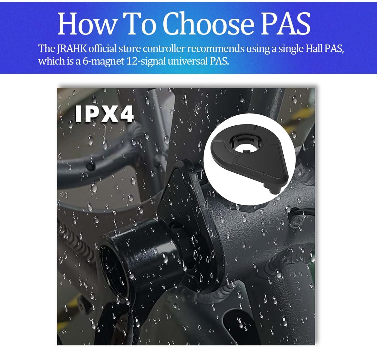
Image 7: Illustration of a recommended PAS (Pedal Assist System) sensor, highlighting its IPX4 water resistance rating and suggesting a 6-magnet 12-signal universal PAS.
5. Operating the LCD Display
The LCD display provides real-time monitoring and control over your e-bike's system. It is compatible with 36V, 48V, 52V, and 60V systems.
5.1. Display Information
The display typically shows the following information:
- Battery Percentage / Level Indicator
- Current Speed (KM/H or MPH)
- Trip Distance / Odometer
- Riding Mode / PAS Level
- Error Codes (if any system faults occur)

Image 8: Close-up of the LCD display's rear, showing a "36V" mark. This indicates the monitor's minimum operating voltage is 36V. Users should confirm actual operating voltage with product specifications.
5.2. Adjusting Parameters
The LCD display allows for adjustment of various parameters. Consult the specific LCD display manual (if provided separately) for detailed instructions on accessing and modifying settings such as wheel size, speed limit, and battery voltage.
6. Key Features and Technologies
6.1. Silent Sine Wave Technology
The controller utilizes default sine wave output, which significantly reduces motor hum by up to 70% compared to traditional square wave controllers. This results in smoother motor starts, quieter operation, and contributes to extended motor life.
6.2. Dual-Mode Motor Control
The controller supports both Hall sensor mode and a sensorless backup mode with motor rotation self-learning. For daily use, the Hall sensor mode is recommended for optimal performance. The sensorless mode serves as a reliable backup in case of Hall sensor damage or compatibility issues, though it may result in mild startup vibration.
6.3. 20A Overload Protection
Equipped with a robust 6-MOSFET design, the controller provides 20A overload protection, allowing it to handle demanding conditions such as steep hills. This feature, combined with configurable high/low level brake signals, enhances safety and system durability.
6.4. Regenerative Braking (EABS Brake System)
The system incorporates regenerative braking capabilities. During downhill coasting or braking, a portion of the kinetic energy is converted back into electrical energy and returned to the battery. The EABS (Electronic Anti-lock Braking System) not only shortens braking distance but also contributes to energy recovery, potentially extending battery range.

Image 9: Visual explanation of Regenerative Braking and the EABS Brake System. It shows kinetic energy conversion to electrical energy during braking and how EABS shortens braking distance and aids in battery charging.
7. Maintenance
To ensure the longevity and optimal performance of your JRAHK controller and display kit, follow these maintenance guidelines:
- Keep Clean: Regularly wipe down the controller and display with a dry, soft cloth to remove dust and dirt.
- Check Connections: Periodically inspect all wiring connections to ensure they are secure and free from corrosion. Loose connections can lead to intermittent operation or damage.
- Moisture Protection: The controller features a PCB conformal coating for moisture and dust resistance. However, avoid submerging the unit in water and protect it from heavy rain. Ensure the LCD waterproof connector is properly sealed.
- Avoid Physical Damage: Protect the controller and display from impacts and extreme temperatures.
8. Troubleshooting
If you encounter issues with your JRAHK controller and display kit, consider the following common troubleshooting steps:
- No Power to Display/Motor:
- Check battery charge level.
- Verify all power connections (battery to controller, controller to display) are secure.
- Ensure the main power switch (if applicable) is on.
- Motor Not Responding to Throttle:
- Check throttle connection to the controller.
- Ensure brake levers are not engaged (some systems cut power when brakes are applied).
- Perform the motor direction self-learning procedure again (Section 4.2).
- Motor Runs Irregularly or with Vibration:
- Verify motor phase wire and Hall sensor connections are correct and secure.
- If Hall sensors are suspected to be damaged, the controller can operate in sensorless mode (note: mild startup vibration may occur).
- LCD Displaying Error Codes:
The LCD display will show specific error codes if a system fault is detected. Consult the LCD display's dedicated manual (if available) for a list of error codes and their corresponding troubleshooting steps. Common errors relate to motor, controller, or battery issues.
If problems persist after attempting these steps, it is recommended to contact JRAHK customer support or a qualified e-bike technician.
9. Warranty and Support
For information regarding product warranty, returns, or technical support, please refer to the documentation included with your purchase or contact the seller directly. Keep your purchase receipt or order number handy for any warranty claims or support inquiries.
For further assistance, you may also visit the official JRAHK website or contact their customer service channels as provided on their product packaging or online listings.
Ask a question about this manual
Ask about setup, troubleshooting, compatibility, parts, safety, or missing instructions. Manuals+ will review the question and use this page’s manual context to help answer it.