1. Overview
The Garosa 45-in-1 Electronics Modules Kit is a comprehensive collection of electronic components designed for learning, prototyping, and developing various projects. This kit is compatible with popular microcontroller platforms, including the Mega 2560 R3 development board.

Image 1.1: All 45 modules of the Garosa Electronics Kit displayed.
Key Features:
- Portability and Organization: The kit features a compact and lightweight design, facilitating transport and use. Components are labeled for identification.
- Universal Compatibility: This kit is designed for compatibility with various microcontroller platforms, including Mega 2560 R3 development boards.
- Comprehensive Module Selection: The kit includes 45 electronic components such as gyroscopes, temperature sensors, infrared receivers, and ultrasonic modules, suitable for diverse projects.
- Component Reliability: Each sensor module is selected for performance and durability, suitable for new projects or as replacements.
- Educational Value: This kit supports learning for both beginners and experienced users, providing components for introductory programming courses and advanced projects.
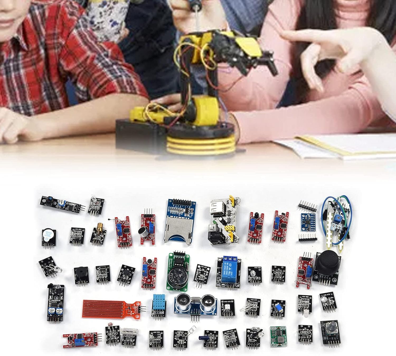
Image 1.2: Example of the kit's application in an educational setting.
2. Components List
This kit includes the following 45 modules, designed for a wide range of electronic and programming applications:

Image 2.1: Detailed view of selected modules from the kit.
- 1 x Breadboard Power Module
- 1 x GY-521 3-Axes Acceleration Gyroscope 6DOF Module
- 1 x MH Real-Time Clock Module
- 1 x HW-498 Analog Temperature Sensor Module
- 1 x HW-495 Hall Magnetic Module
- 1 x HW-489 Infrared Transmitting Sensor Module
- 1 x HC-SRO4 Ultrasonic Module
- 1 x HW-484 Large Reed Module
- 1 x HW-480 Red and Green Dual Color LED Module
- 1 x HW-479 Tri-color Light RGB Module
- 1 x HW-203 SD Card Reader Module
- 1 x HW-499 Magic Light Cup Module
- 1 x HW-488 Smart Car Obstacle Avoidance Sensor
- 1 x HW-486 Photoresistor Module
- 1 x HW-040 260 Degree Spiral Encoder Module
- 1 x HW-511 Tracking Module
- 1 x HW-485 High-Sensitivity Microphone Sensor Module
- 1 x HW-478 Three-Color Full-Color LED Smd Module
- 1 x HW-491 Mystical/Fantasy Module
- 1 x HW-502 Finger Detection Heartbeat Module
- 1 x HW-512 Active Buzzer Module
- 1 x HW-038 Water Depth Detection Module
- 1 x HW-477 Two-Color LED Common Cathode Module
- 1 x HW-080 Soil Probe Module + HW-103 Temperature and Humidity Module (combined)
- 1 x MP1584 Board 3A Regulated Power Supply Module
- 1 x HW-513 Vibration Switch Module
- 1 x HW-487 Light Interruption Sensor Module
- 1 x HW-494 Metal Touch Module
- 1 x HW-509 Linear Magnetic Hall Sensor
- 1 x HW-501 Tilt Switch Module
- 1 x HW-490 Infrared Sensor Receiving Module
- 1 x HW-483 Micro Switch Module
- 1 x HW-500 Tap Sensor Module
- 1 x HW-505 Switch Module
- 1 x HW-497 Mini Reed Module
- 1 x HW-496 Microphone Amplifier Module
- 1 x HW-492 Hall Sensor Module
- 1 x HW-507 Single Bus Digital Temperature and Humidity Sensor
- 1 x HW-508 Small Passive Buzzer Module
- 1 x HW-504 Dual-Axes Button Remote Lever
- 1 x HW-481 Colorful Automatic Module
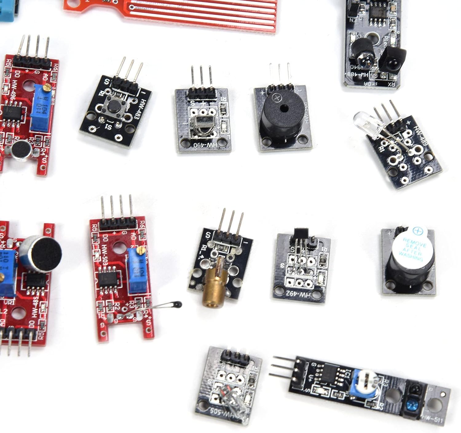
Image 2.2: Assortment of smaller modules from the kit.

Image 2.3: Additional modules, including power supply and various switches.
3. Setup Instructions
This section provides general guidelines for setting up and connecting the modules. Specific wiring and programming will depend on your project and chosen microcontroller (e.g., Mega 2560 R3).
3.1 Unpacking and Identification
- Carefully unpack all components from the packaging.
- Refer to the 'Components List' section to identify each module. Most modules are labeled with their model numbers (e.g., HW-485, HC-SRO4).
- Inspect each module for any visible damage.
3.2 Basic Connections
- Power Supply: Use the Breadboard Power Module or MP1584 Board 3A Regulated Power Supply Module to provide stable power to your breadboard or microcontroller. Ensure correct voltage (typically 3.3V or 5V) is selected for your components.
- Microcontroller Connection: Connect the modules to your chosen microcontroller (e.g., Mega 2560 R3) using jumper wires. Pay close attention to VCC (power), GND (ground), and data pins (digital/analog I/O, I2C, SPI, etc.).
- Breadboard Usage: For prototyping, utilize a breadboard to make temporary connections between modules and the microcontroller without soldering.
- Refer to Datasheets: For detailed pinouts and electrical characteristics of individual modules, consult their respective datasheets or online resources.
3.3 Safety Precautions
- Always double-check wiring before applying power to prevent damage to components.
- Avoid short circuits.
- Handle components by their edges to minimize static discharge.
- Do not exceed the specified voltage or current ratings for any module.
4. Operating Principles
Operating the modules involves programming your microcontroller to interact with them. This kit is ideal for use with development environments like the Arduino IDE.
4.1 Programming Your Microcontroller
- Software Setup: Install the necessary IDE (e.g., Arduino IDE) and any required board support packages or libraries for your microcontroller (e.g., Mega 2560 R3).
- Code Development: Write or adapt code to interface with the specific module(s) you are using. Many modules have existing libraries or example code available online.
- Upload Code: Connect your microcontroller to your computer and upload the compiled code.
4.2 Module Interaction
- Sensors: Read data from input modules (e.g., GY-521 Gyroscope, HC-SRO4 Ultrasonic, Photoresistor) to detect environmental conditions or physical interactions.
- Actuators/Outputs: Control output modules (e.g., LED modules, Buzzer Module, Relay Module) based on sensor readings or programmed logic.
- Communication: Utilize modules like the SD Card Reader for data logging or other communication protocols.
5. Maintenance
Proper maintenance ensures the longevity and reliable operation of your electronic modules.
- Storage: Store modules in a dry, cool environment, away from direct sunlight and extreme temperatures. Use anti-static bags or containers to protect them from electrostatic discharge (ESD).
- Cleaning: If necessary, gently clean modules with a soft, dry brush or a lint-free cloth. Avoid using liquids or abrasive materials.
- Handling: Always handle modules by their edges. Avoid touching exposed pins or sensitive components directly.
- Inspection: Periodically inspect modules for bent pins, loose connections, or any signs of corrosion or damage.
6. Troubleshooting
If you encounter issues with your modules, consider the following troubleshooting steps:
- No Power:
- Check power supply connections and ensure the power module is correctly configured (e.g., 5V output).
- Verify that the microcontroller is powered and functioning.
- Module Not Responding:
- Review all wiring connections for correctness and ensure they are secure.
- Confirm that the correct pins on the microcontroller are being used for the module.
- Check your code for logical errors or incorrect library usage.
- Ensure the module is compatible with the voltage level of your microcontroller (e.g., 3.3V vs. 5V).
- Incorrect Readings:
- Calibrate sensors if applicable.
- Check for environmental interference (e.g., light affecting photoresistors, magnetic fields affecting Hall sensors).
- Verify that the correct data interpretation is applied in your code.
- Component Damage:
- Look for burnt components, discolored areas, or unusual odors.
- If a module is suspected to be faulty, try replacing it with a known working one if available.
7. Specifications
General specifications for the Garosa 45-in-1 Electronics Modules Kit:
| Attribute | Value |
|---|---|
| Manufacturer | Garosa |
| Item Weight | 6.5 ounces |
| Package Dimensions | 5.51 x 3.54 x 0.79 inches |
| Item Model Number | Garosanc4f8bevmt |
| Power Source | AC/DC |
| Batteries Required? | No |
| Date First Available | June 30, 2025 |
8. Warranty and Support
For technical assistance, product inquiries, or support regarding your Garosa 45-in-1 Electronics Modules Kit, please refer to the manufacturer's contact information or the retailer's support channels.
Manufacturer Contact Information:
Garosa
Please consult the original product packaging or purchase documentation for specific contact details or warranty terms.