1. Introduction
This manual provides comprehensive instructions for the proper setup, operation, and maintenance of the LEAIENINJS XY-PWM3 3-Way Pulse Frequency Duty Cycle Adjustable Signal Generator. This module is designed to generate square and rectangular wave signals with adjustable frequency and duty cycle across three independent channels. It is suitable for various electronic applications, including motor speed control, LED dimming, signal generation, and experimental circuits.
2. Product Overview
The XY-PWM3 module features an intuitive interface with an LCD display and tactile buttons for easy parameter adjustment. It provides three independent PWM outputs, each with configurable frequency and duty cycle.
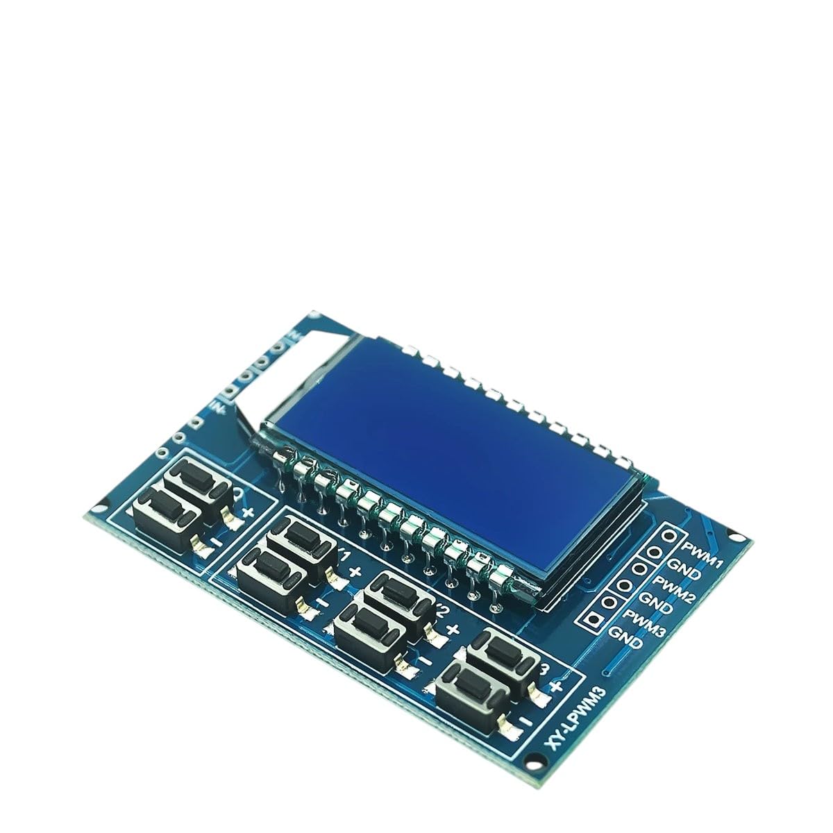
Figure 1: LEAIENINJS XY-PWM3 Module. This image displays the LEAIENINJS XY-PWM3 module, featuring an LCD screen for parameter display, multiple push-buttons for adjustment, and clearly labeled output terminals for PWM1, PWM2, and PWM3, along with corresponding GND connections. The module's compact design is suitable for integration into various electronic projects.
Key Components:
- LCD Display: Shows current frequency, duty cycle, and channel selection.
- Control Buttons: Used for navigating menus, adjusting parameters, and selecting channels. Typically labeled with '+', '-', 'SET', and channel selection buttons.
- PWM Output Terminals: Three sets of terminals (PWM1, PWM2, PWM3) with corresponding Ground (GND) connections for signal output.
- Power Input: DC power input terminals (usually 5V-30V).
3. Features
- Three independent PWM output channels.
- Adjustable frequency range (e.g., 1Hz to 150kHz).
- Adjustable duty cycle range (e.g., 0% to 100%).
- High-resolution LCD display for clear parameter viewing.
- Simple button interface for easy operation.
- Wide operating voltage range.
- Non-volatile storage for settings.
4. Specifications
| Parameter | Value |
|---|---|
| Operating Voltage | DC 5V - 30V |
| Frequency Range | 1Hz - 150kHz |
| Duty Cycle Range | 0% - 100% |
| Number of Channels | 3 independent channels |
| Output Amplitude | Equal to input voltage |
| Output Current | Up to 30mA per channel (sink/source) |
| Dimensions | Approx. 79mm x 43mm x 26mm |
5. Setup
- Power Connection: Connect a DC power supply (5V-30V) to the module's power input terminals. Ensure correct polarity (+ to +, - to -).
- Output Connection: Connect your target device (e.g., motor driver, LED circuit) to the desired PWM output terminals (PWM1, PWM2, or PWM3) and their respective GND terminals.
- Initial Power On: Once powered, the LCD display will illuminate, showing the default or previously saved settings for the active PWM channel.
Caution: Ensure all connections are secure and correct before applying power to prevent damage to the module or connected devices.
6. Operating Instructions
6.1. Channel Selection
- Press the SET button briefly to cycle through the three PWM channels (PWM1, PWM2, PWM3). The active channel will be indicated on the LCD.
6.2. Adjusting Frequency
- Select the desired PWM channel using the SET button.
- Press and hold the SET button for approximately 2 seconds until the frequency value starts blinking on the LCD. This indicates frequency adjustment mode.
- Use the + and - buttons to increase or decrease the frequency. Short presses adjust in small increments, long presses adjust in larger steps.
- Press the SET button again briefly to confirm the frequency and switch to duty cycle adjustment, or wait a few seconds for it to automatically save and exit adjustment mode.
6.3. Adjusting Duty Cycle
- Ensure the desired PWM channel is selected.
- If in frequency adjustment mode, press SET briefly to switch to duty cycle adjustment (the duty cycle value will blink). If not in adjustment mode, press and hold SET until frequency blinks, then press SET again.
- Use the + and - buttons to increase or decrease the duty cycle (0% to 100%).
- Press the SET button again briefly to confirm the duty cycle and exit adjustment mode, or wait a few seconds for it to automatically save and exit.
6.4. Saving Settings
All adjusted frequency and duty cycle settings for each channel are automatically saved to non-volatile memory after a few seconds of inactivity in adjustment mode, or upon exiting adjustment mode by pressing the SET button.
7. Maintenance
- Cleaning: Use a soft, dry cloth to clean the module. Avoid using liquids or abrasive cleaners.
- Storage: Store the module in a dry, dust-free environment when not in use.
- Handling: Handle the module with care to avoid physical damage to components or connections.
- Power Supply: Always use a stable and appropriate DC power supply within the specified voltage range.
8. Troubleshooting
| Problem | Possible Cause | Solution |
|---|---|---|
| Module does not power on. | Incorrect power connection, power supply failure, voltage outside range. | Check power supply voltage and polarity. Ensure connections are secure. Try a different power supply. |
| No PWM output signal. | Incorrect wiring to target device, duty cycle set to 0%, module fault. | Verify output wiring. Check if duty cycle is set above 0%. Test with a multimeter. |
| Parameters cannot be adjusted. | Not in adjustment mode, faulty buttons. | Press and hold SET to enter adjustment mode. Ensure buttons are functioning correctly. |
| LCD display is blank or garbled. | Power issue, module fault. | Check power supply. Power cycle the module. If issue persists, contact support. |
9. Warranty and Support
LEAIENINJS products are manufactured to high-quality standards. For warranty information, technical support, or service inquiries, please refer to the contact information provided with your purchase or visit the official LEAIENINJS website. Please have your product model (XY-PWM3) and purchase details ready when contacting support.
This manual is subject to change without prior notice. The latest version can be found on the manufacturer's website.


