1. Introduction
This manual provides detailed instructions for the safe and effective use of your K&F CONCEPT Professional Fluid Head BV50. Please read this manual thoroughly before operating the product and retain it for future reference.
The K&F CONCEPT BV50 is a professional fluid video head designed for smooth and stable camera movements, supporting equipment up to 8kg (17.6 lbs). It features 360° panoramic rotation and a tilt range of -75° to +90°.
2. Product Overview and Components
Familiarize yourself with the various parts of your fluid head:
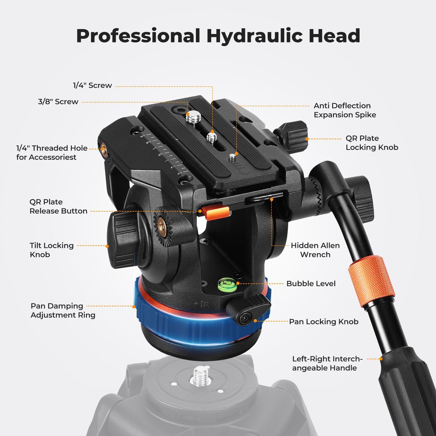
Figure 1: Labeled diagram of the K&F CONCEPT BV50 Professional Fluid Head, showing key components such as the 1/4" screw, 3/8" screw, QR plate locking knob, tilt locking knob, pan damping adjustment ring, pan locking knob, bubble level, hidden Allen wrench, QR plate release button, anti-deflection expansion spike, and left-right interchangeable handle.
- 1/4" & 3/8" Screws: For attaching cameras and accessories to the quick release plate.
- QR Plate Locking Knob: Secures the quick release plate in place.
- Anti-Deflection Expansion Spike: Prevents plate rotation.
- QR Plate Release Button: Allows for quick removal of the camera plate.
- Tilt Locking Knob: Adjusts and locks the vertical tilt angle.
- Pan Damping Adjustment Ring: Controls the resistance of horizontal panning.
- Pan Locking Knob: Locks the fluid head in a horizontal position.
- Bubble Level: Assists in achieving a level setup.
- Hidden Allen Wrench: Integrated tool for adjustments.
- Left-Right Interchangeable Handle: Provides control for panning and tilting, can be mounted on either side.
3. Setup
3.1 Mounting the Fluid Head to a Tripod
- Ensure your tripod is stable and capable of supporting the fluid head and your camera equipment. The fluid head base has a 3/8" thread for tripod attachment.
- Screw the fluid head onto the tripod's mounting screw until it is securely fastened.
- Use the bubble level on the fluid head to ensure the head is level before attaching your camera.
3.2 Attaching Your Camera
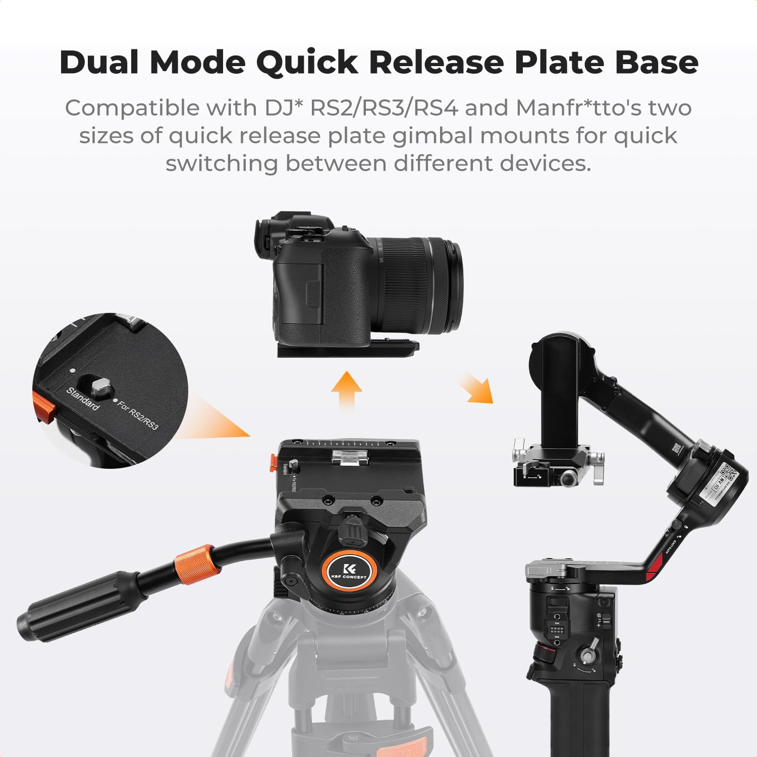
Figure 2: Illustration of the quick release plate mechanism, demonstrating how to press the button to install and release the plate.
- Locate the quick release plate. It features both 1/4" and 3/8" screws for various camera types.
- Attach the quick release plate to the bottom of your camera by screwing the appropriate screw (1/4" or 3/8") into the camera's tripod socket. Ensure it is tightened securely.
- To install the camera with the attached quick release plate onto the fluid head:
- Ensure the QR Plate Locking Knob is loosened.
- Press the QR Plate Release Button.
- Slide the quick release plate with your camera into the receiver on the fluid head until it clicks into place.
- Tighten the QR Plate Locking Knob to secure the camera.
- To remove the camera:
- Loosen the QR Plate Locking Knob.
- Press and hold the QR Plate Release Button.
- Slide the quick release plate with your camera out of the receiver.

Figure 3: The fluid head's quick release system is compatible with DJI RS2/RS3/RS4 and Manfrotto quick-release plates, allowing for seamless switching between different camera setups and gimbals.
4. Operating Instructions
4.1 Panoramic Rotation (360°)
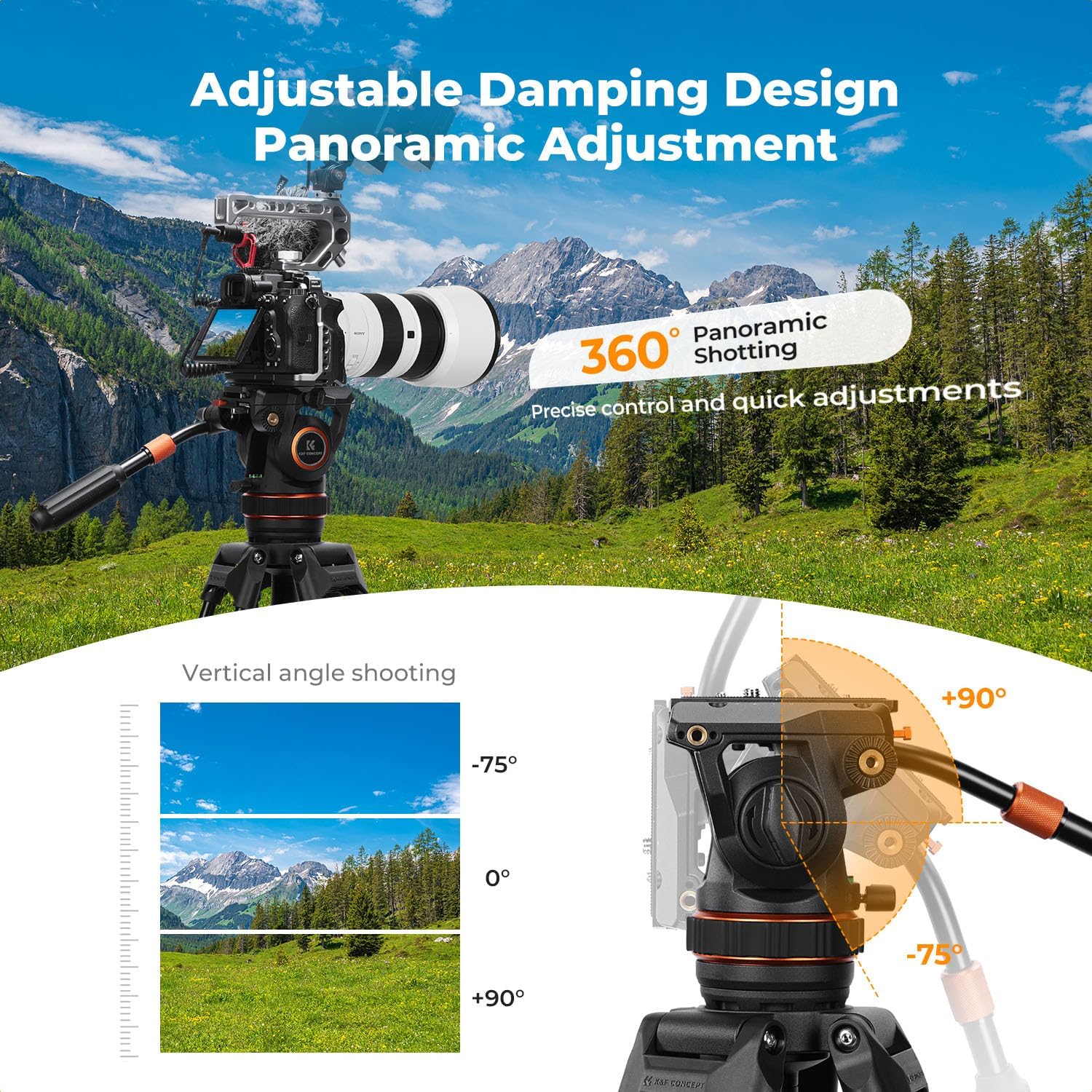
Figure 4: Demonstrates the 360° panoramic shooting capability and the vertical tilt range from -75° to +90°.
The fluid head allows for a full 360° horizontal rotation for panoramic shots.
- To pan the camera, loosen the Pan Locking Knob.
- Adjust the Pan Damping Adjustment Ring to achieve your desired level of resistance for smooth movement.
- Gently move the handle to rotate the camera horizontally.
- Once the desired position is reached, tighten the Pan Locking Knob to secure the head.
4.2 Tilt Adjustment (-75° to +90°)
The fluid head offers a tilt range from -75° (downward) to +90° (upward).
- To tilt the camera, loosen the Tilt Locking Knob.
- Gently move the handle to adjust the camera's vertical angle.
- Once the desired angle is achieved, tighten the Tilt Locking Knob to secure the head.
4.3 Handle Adjustment

Figure 5: Detailed view of the adjustable two-section telescopic handle (23.5cm-37.5cm), the multi-functional concealed Allen wrench, and the expandable interface at the ball head.
The telescopic handle can be adjusted for length (23.5cm-37.5cm) and can be mounted on either the left or right side of the fluid head for user comfort and versatility.
- To adjust the handle length, twist the locking collar on the handle, extend or retract to the desired length, and then twist to lock.
- To change the handle's side, unscrew it from its current position and screw it into the mounting point on the opposite side of the fluid head.
5. Maintenance
Proper maintenance ensures the longevity and optimal performance of your fluid head.
- Cleaning: Use a soft, dry cloth to wipe down the fluid head after each use. For stubborn dirt, a slightly damp cloth can be used, followed by immediate drying. Avoid harsh chemicals or abrasive materials.
- Lubrication: The fluid damping system is sealed and does not require user lubrication. Do not attempt to disassemble the fluid head for lubrication.
- Storage: Store the fluid head in a clean, dry environment, away from extreme temperatures and humidity.
- Inspection: Periodically check all screws and knobs to ensure they are tight. The integrated Allen wrench can be used for minor adjustments.
6. Troubleshooting
If you encounter issues with your K&F CONCEPT BV50 Fluid Head, refer to the following common problems and solutions:
- Movement is not smooth:
- Ensure all locking knobs (Pan and Tilt) are sufficiently loosened.
- Check the Pan Damping Adjustment Ring for proper setting. Adjust it to a lighter setting if movement feels stiff.
- Verify that the fluid head is securely mounted to the tripod and the camera is securely attached to the quick release plate.
- Camera feels unstable:
- Confirm that the quick release plate is fully seated and the QR Plate Locking Knob is tightened.
- Ensure the camera is properly balanced on the quick release plate.
- Check that the fluid head is securely attached to a stable tripod.
- Verify that your camera and lens combination does not exceed the maximum load capacity of 8kg (17.6 lbs).
- Quick release plate is difficult to remove/install:
- Ensure the QR Plate Locking Knob is fully loosened.
- Press the QR Plate Release Button firmly while sliding the plate.
If problems persist, please contact K&F CONCEPT customer support for assistance.
7. Specifications
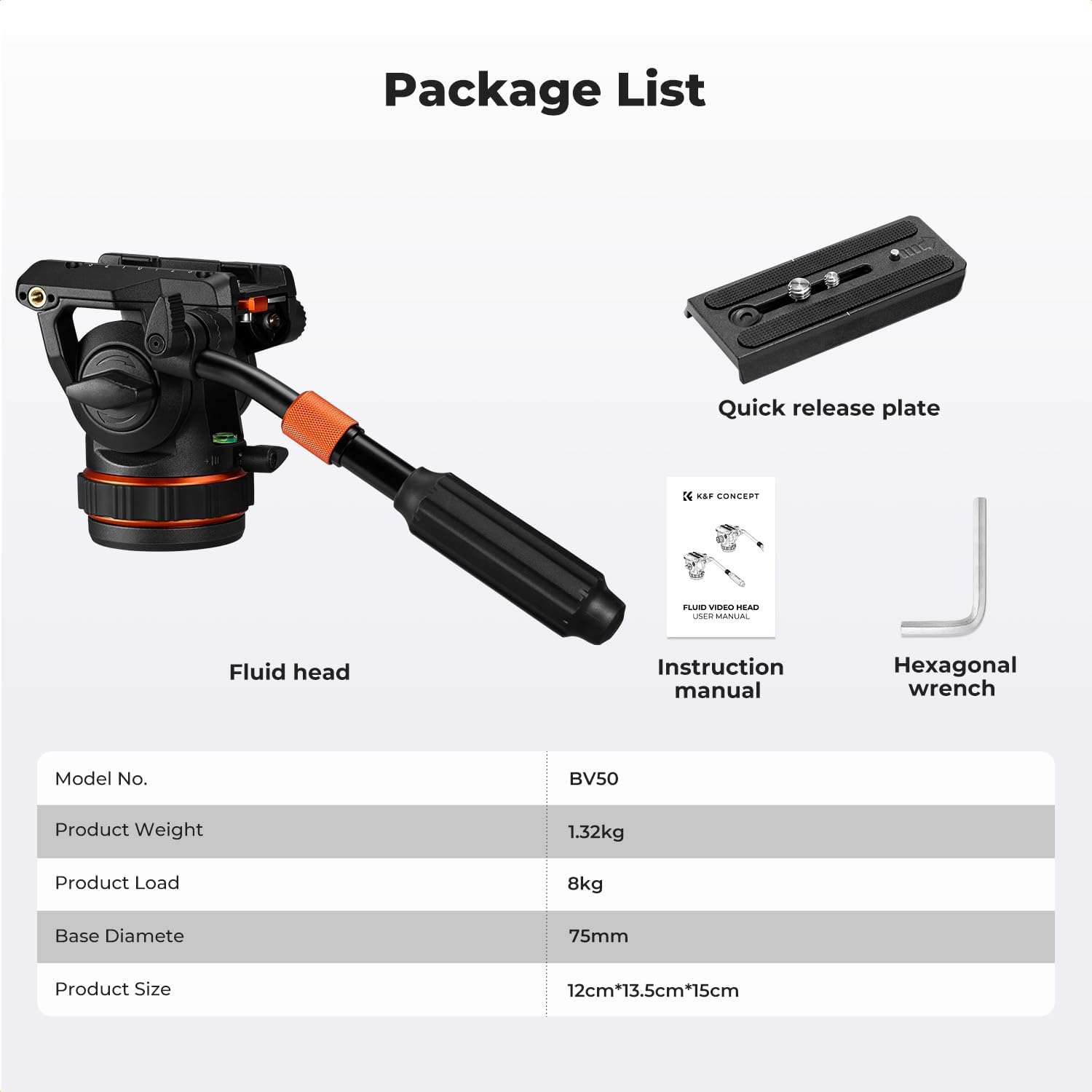
Figure 6: Overview of the K&F CONCEPT BV50 package contents and key product specifications.
| Feature | Detail |
|---|---|
| Model Number | BV50 |
| Max Load Capacity | 8 kg (17.6 lbs) |
| Net Weight | 1.005 kg (2.22 lbs) |
| Pan Range | 360° |
| Tilt Range | -75° to +90° |
| Base Diameter | 75mm |
| Quick Release Plate Compatibility | DJI RS2/RS3/RS4 & Manfrotto compatible |
| Mounting Screws | 1/4" & 3/8" on QR plate |
| Base Thread | 3/8" |
| Handle Length Range | 23.5cm - 37.5cm |
8. What's in the Box
- K&F CONCEPT Professional Fluid Head BV50 x 1
- Quick Release Plate x 1
- Instruction Manual x 1
- Hexagonal Wrench x 1
9. Warranty and Support
K&F CONCEPT products are manufactured to high-quality standards. For information regarding warranty coverage, please refer to the warranty card included with your product or visit the official K&F CONCEPT website.
For technical support, troubleshooting assistance, or inquiries about replacement parts, please contact K&F CONCEPT customer service through their official channels. Please have your product model number (BV50) and purchase details ready when contacting support.
Online Support: Visit the K&F CONCEPT Store on Amazon
10. Official Product Videos
No official product videos from the seller were found in the provided data.